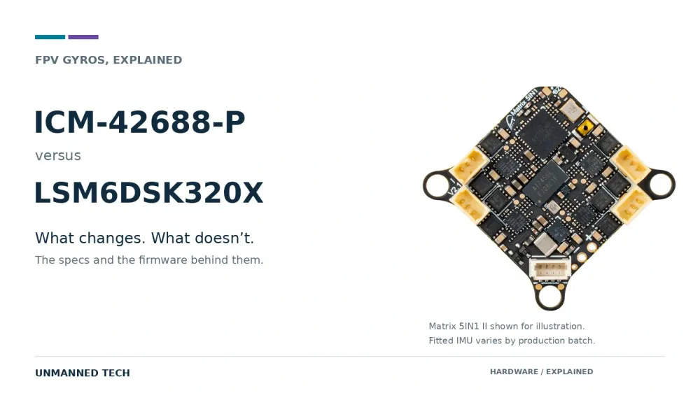
Published by Unmanned Tech
A wider measuring range is useful. An impressive spec sheet still cannot tell you how a flight controller will fly.
A flight-controller manufacturer can change the fitted gyro between production batches. Before treating that as an upgrade or a downgrade, check the exact sensor and the firmware supplied for that board revision.
The TDK InvenSense ICM-42688-P and STMicroelectronics LSM6DSK320X make a good example. ST's chip has a wider angular-rate range, a separate high-g accelerometer and embedded machine-learning hardware. TDK's chip has the lower published gyro noise density. Neither description settles which complete board will fly better.
Our buying advice: choose the board with the right connections, documented firmware for its exact hardware revision and a sensible installation. Use the gyro as part of that decision, not the whole decision.
First, a correction to the noise claim
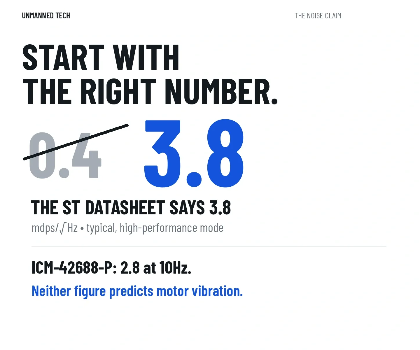
A gyro noise density of 0.4 mdps/√Hz would make the ST chip look unusually quiet. That is not the figure in ST's LSM6DSK320X datasheet.
ST specifies 3.8 mdps/√Hz typical in high-performance mode. TDK specifies 2.8 mdps/√Hz typical at 10Hz for the ICM-42688-P. Here, 10Hz is the frequency at which noise density is specified, not the sensor's output-data rate.
Noise density describes the sensor's background measurement noise per square root of bandwidth. The full unit is millidegrees per second per square root hertz. You do not need to memorise it; the useful distinction is that it is a sensor-noise specification, not a measurement of what your motors and frame will do to the signal.
The ICM has the lower published number. That does not prove it will produce the cleaner signal on a vibrating aircraft. The manufacturers' headline figures are not a matched test of two flight controllers, and they do not include your installation.
What is actually different?
Both devices are inertial measurement units, or IMUs. They contain a gyroscope to measure rotation and accelerometers to measure specific force, the acceleration-related quantity you normally see expressed in g.
The following are chip capabilities, not a promise that every flight-controller firmware uses them.
Datasheet figures: ranges, rates, buffers and current
| Capability | TDK ICM-42688-P | ST LSM6DSK320X |
|---|---|---|
| Maximum selectable gyro range | ±2000°/s | ±4000°/s |
| Published typical gyro noise density | 2.8 mdps/√Hz at 10Hz | 3.8 mdps/√Hz in high-performance mode |
| Low-g accelerometer range | Up to ±16g | Up to ±16g |
| Separate high-g acceleration channel | No | Up to ±320g |
| Maximum documented gyro output-data rate | 32kHz | 8kHz in high-accuracy ODR mode; 7.68kHz in the standard rate set |
| On-chip FIFO data buffer | 2KB | Up to 4.5KB |
| Example quoted six-axis current | 0.88mA, low-noise mode | 0.67mA, combo high-performance mode |
Sources: TDK's datasheet and ST's datasheet. Modes and test conditions differ; these figures are not a controlled power or noise benchmark. FIFO means the chip's short-term data buffer, not your flight controller's Blackbox storage.
The longer part number LSM6DSK320XTR is ST's tape-and-reel ordering code for the LSM6DSK320X. The extra letters are not a separate FPV performance tier.
±4000°/s gives headroom, not sharper sticks
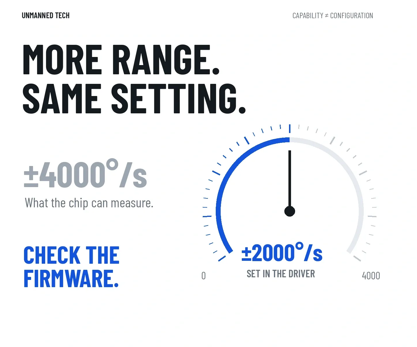
The gyro's range tells you how fast it can measure rotation before the signal reaches its limit. If the aircraft rotates beyond that limit, the reading clips: it can no longer represent the true angular rate.
A wider range can help capture very fast motion, including uncommanded tumbles. It does not make the quad rotate faster, and it does not improve tracking simply because you selected a larger number.
ST's datasheet also shows a resolution trade-off at the register output: its sensitivity is 70 mdps per least-significant bit at ±2000°/s and 140 mdps per bit at ±4000°/s. In plain English, the wider setting uses larger measurement steps. That is a reason for firmware developers to choose settings carefully, not a reason to declare the chip unsuitable.
Available range and configured range are different things. In fact, Betaflight 2026.6.2's LSM6DSK320X driver selects ±2000°/s, not the chip's ±4000°/s maximum. Buying the wider-range sensor does not automatically give your quad wider-range readings.
±320g is not a crash-proofing feature
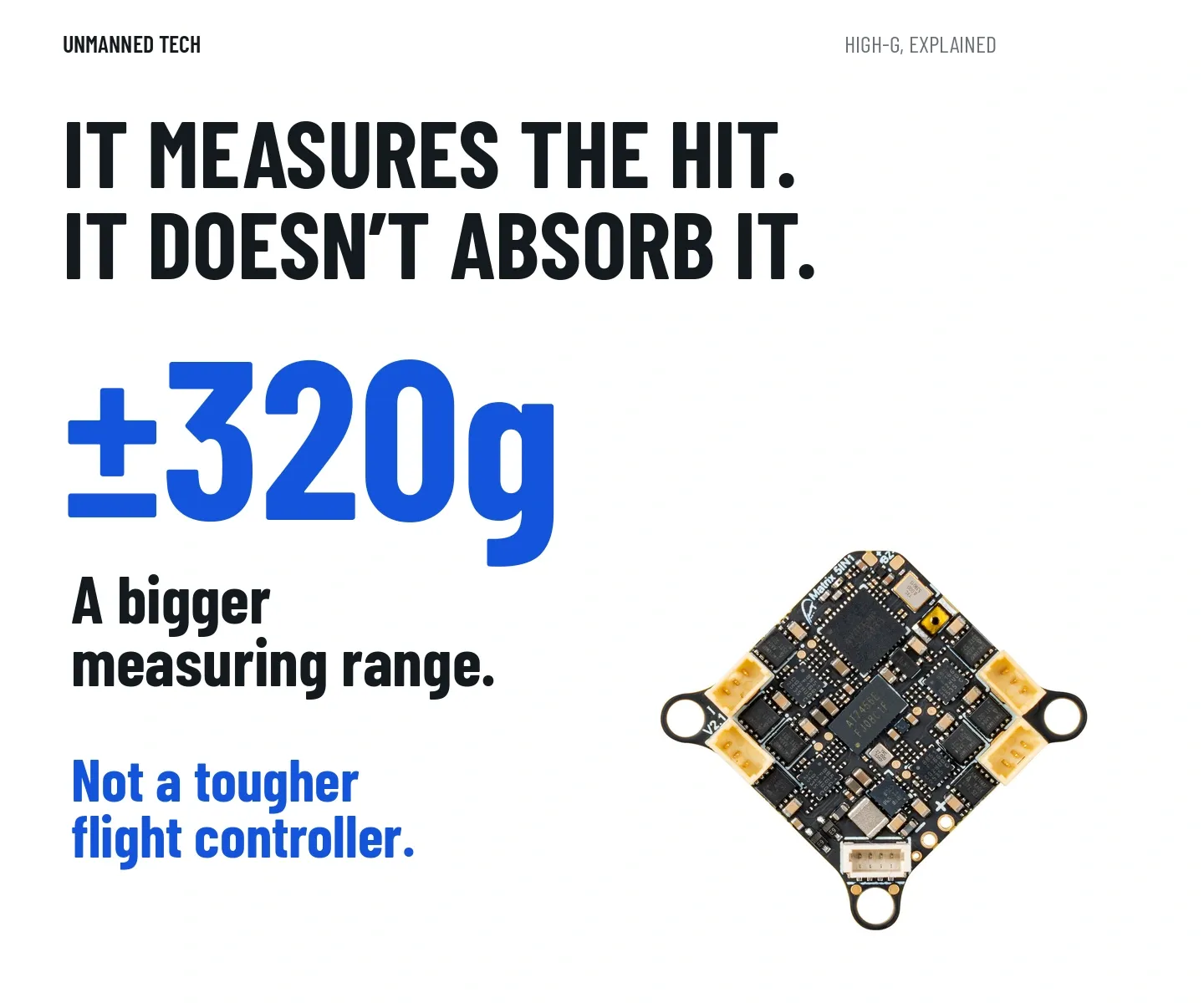
The ST device has separate low-g and high-g acceleration channels. Its high-g channel can measure much larger acceleration events before clipping. That can be useful for recording impacts or building event-detection features.
It does not extend the gyroscope's angular-rate range. It does not make the PCB, solder joints or frame tougher. Nor does measuring a crash mean a flight controller can recover from it.
ST describes its new gyro architecture as having a fully differential readout and enhanced mechanical symmetry, designed for improved vibration immunity. That is relevant to FPV. It is also a different claim from the high-g accelerometer specification.
A convincing crash or vibration comparison would need tests of the complete boards under defined conditions. We have not conducted those tests, so we would not recommend an ST-equipped board as the tougher choice for bando flying merely because it says ±320g.
What determines stick feel?
The sensor measures motion. Filters reduce unwanted signal, with consequences for delay. The flight controller compares the measured angular rate with the pilot's requested rate, then changes motor output. The aircraft moves and the process repeats.
That gives board design, mounting, firmware, filtering and tuning plenty of opportunities to change the result.
Claims that the ICM always feels razor-sharp, or that the ST always needs lower P and I gains, need comparable flight logs and a documented setup. A report from one quad can help diagnose that quad. It is not a universal tuning prescription for every board using the same sensor.
We would not start a new build by reducing gains because of the letters printed on its IMU. Start with the board manufacturer's supported setup. If it behaves badly, inspect the mechanics and use Blackbox flight logs to work out what is happening before making tuning changes.
Sensor rate is not control-loop rate
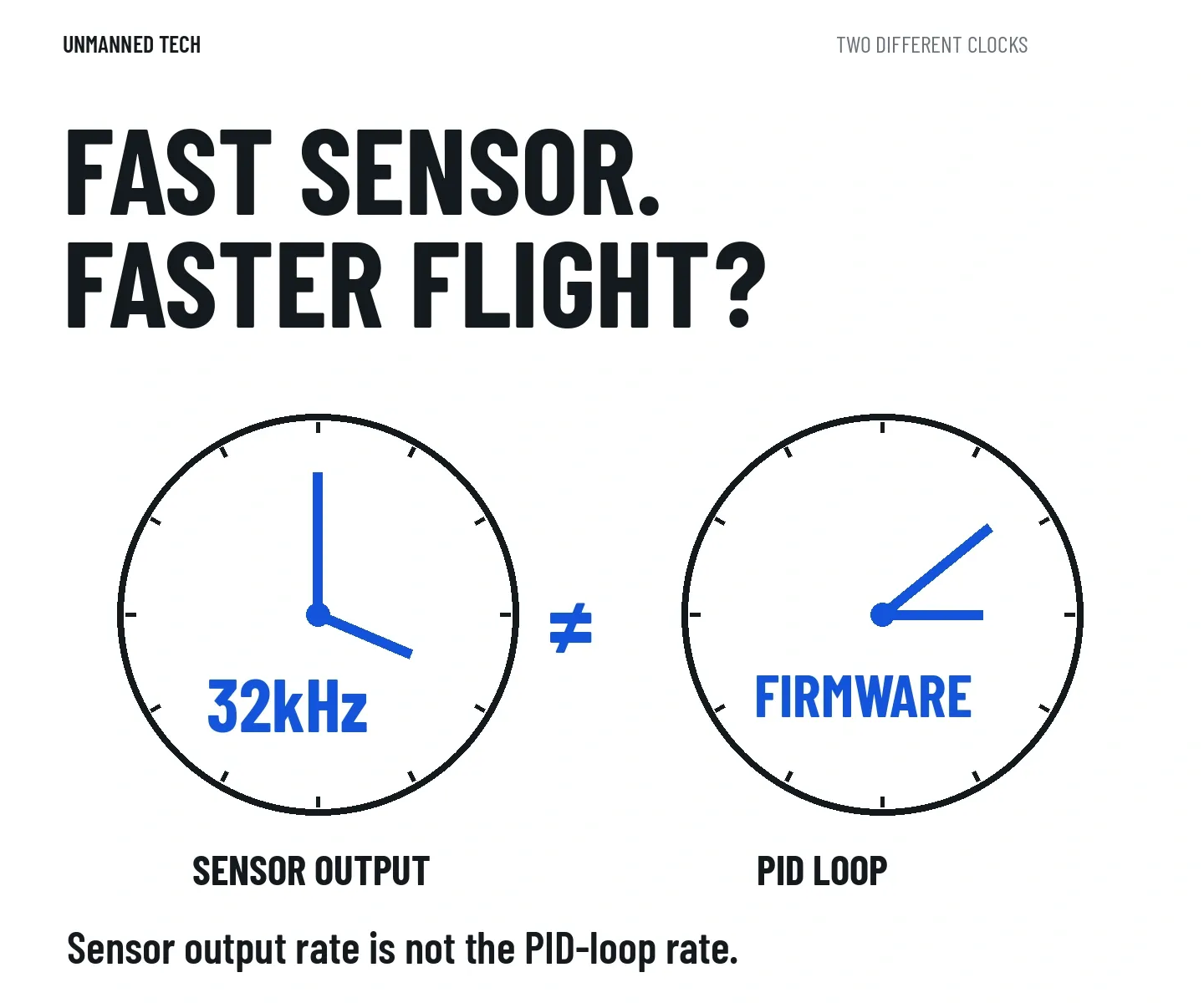
The ICM-42688-P supports output-data rates up to 32kHz. ST lists 7.68kHz in its standard rate set, but Table 22 of its datasheet also documents an 8kHz setting in high-accuracy ODR mode. Betaflight 2026.6.2's ST driver selects that 8kHz mode. Calling 7.68kHz the chip's absolute maximum would miss a useful detail; treating TDK's 32kHz maximum as an automatic flight-performance win would overstate another.
A sensor's output-data rate is how often it can supply measurements. The PID loop rate is how often the flight controller calculates corrections. The firmware decides how those measurements are configured and consumed, and the available processing time matters too.
ST's “quad-channel” description does not mean four gyros averaging away noise. It refers to separate processing paths for user-interface motion data, optical image stabilisation, electronic image stabilisation and high-g acceleration. The camera-related names describe chip capabilities, not proof that your FC uses those paths for video stabilisation.
The firmware check matters more than the logo
LSM6DSK320X support appears in the official Betaflight 2026.6.1 release notes, and its driver is present in 2026.6.2. This is released support, not merely a proposed addition on the development branch. It still does not prove that any firmware image with a familiar board name suits your hardware.
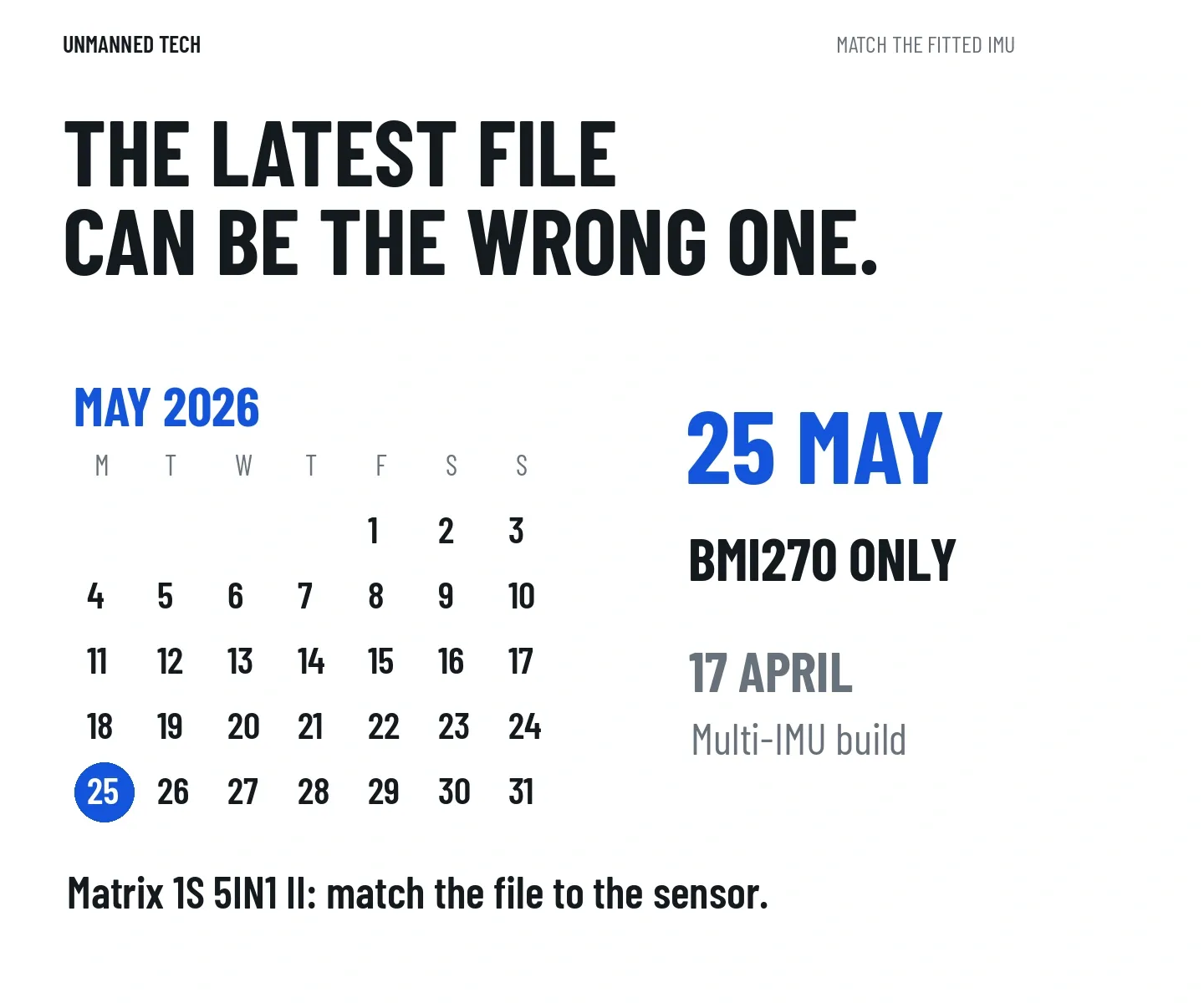
BETAFPV's Matrix 1S 5IN1 II firmware page shows why: its April 2026 manufacturer build supports several IMUs, while its May build is labelled only for the BMI270 and includes a sensor-specific heading offset. Newer in the download list does not necessarily mean suitable for your batch.
Before updating, check the manufacturer's instructions for the exact board revision and fitted IMU. Keep the original firmware information and a configuration backup. If the manufacturer specifies a custom build for your hardware, do not assume the similarly named generic target is interchangeable.
A sensor comparison cannot replace that check. A capable IMU that the installed firmware cannot detect is not much use as a flight controller.
Does the ST chip's AI fly the quad?
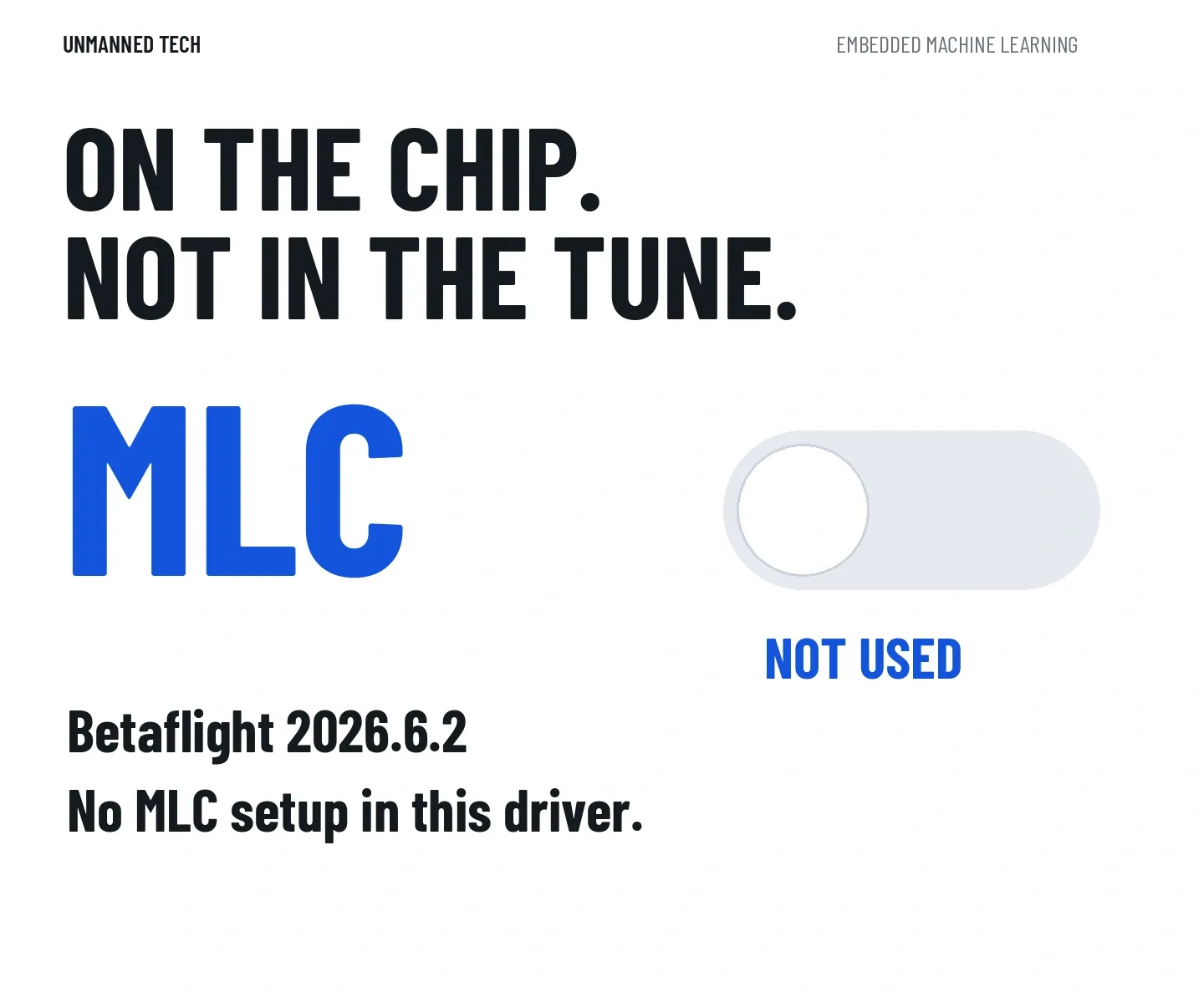
ST includes a finite state machine and a machine learning core. The datasheet describes configurable motion detection and decision-tree processing: the chip can classify patterns and report results without sending every task to the main processor.
That is useful hardware for developers. In the Betaflight 2026.6.2 driver we checked, the ST chip uses its ordinary ±16g accelerometer path, not its ±320g channel. We found no machine-learning model setup or classification-result handling in that driver. Its high-g and AI specifications therefore should not be sold as enabled Betaflight crash-recovery or tuning features.
The ICM-42688-P is not entirely devoid of on-chip motion features either. TDK documents its APEX motion-processing functions, including motion detection and a pedometer. Neither chip's feature list should be mistaken for a list of features enabled in your quad.
Which one would we choose?
For an existing quad that flies well, we would not replace a working flight controller just to change between these two IMUs. The specification differences do not establish that the replacement will fly better.
For a new build, an ICM-42688-P board can be a sensible choice when its layout, firmware and support suit the aircraft. Its lower published gyro noise density is a useful specification, but it does not grant permission to remove filtering or ignore mechanical vibration.
An LSM6DSK320X board also deserves consideration when the manufacturer documents firmware support for that revision. Its wider angular-rate range and vibration-focused architecture are relevant engineering features. The high-g channel and machine learning core are reasons for developers to explore it, rather than flight benefits to assume at checkout.
If two otherwise suitable boards use different IMUs, ask which has clearer firmware documentation, the connections your build needs and useful logging for troubleshooting. Those answers are more actionable than a promise of “locked-in feel”.
Before choosing a replacement, identify what your present board cannot do. If the answer is simply that another gyro has appeared, keep flying it.