Demystifying Modern VTX Control
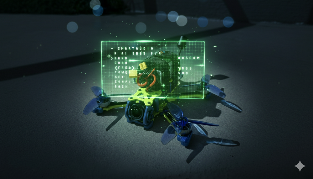
The ability to remotely control a video transmitter (VTX) is a cornerstone of the modern FPV experience. Protocols like SmartAudio, originally developed by TBS, have revolutionized how pilots manage their video feed, offering the convenience of changing channels, bands, and power levels directly from their radio transmitter via an On-Screen Display (OSD). This eliminates the cumbersome process of using physical buttons and interpreting LED flashes on the VTX itself—a critical advantage in both casual flying and competitive racing.
However, the landscape of VTX control has evolved significantly. With the release of Betaflight 4.1, the firmware underwent a fundamental shift: it moved away from having VTX frequency and power settings hardcoded within the firmware itself. This change introduced a new, mandatory configuration layer known as the VTX Table. This system was developed to address the unsustainable challenge of maintaining an ever-expanding list of VTX-specific settings. By offloading this responsibility to the user, Betaflight created a more flexible and future-proof system, but also one that requires a more deliberate setup process.
This guide provides an exhaustive, expert-level walkthrough for configuring SmartAudio VTX control on the latest Betaflight 4.5+ firmware. It covers every stage of the process, from hardware selection and wiring to the intricacies of VTX Tables and advanced troubleshooting.
Section 1: Pre-Flight Checklist: Hardware and Protocol Essentials
Before any physical installation or software configuration, a foundational understanding of your hardware and its protocols is essential. Errors at this stage are the most common source of failure.
Understanding the Protocols: SmartAudio vs. IRC Tramp
Two protocols dominate the analog FPV landscape for VTX control: SmartAudio (SA) and IRC Tramp. While both achieve the same end goal, they are distinct, proprietary protocols and are not interchangeable. You must select the correct protocol for your specific VTX within Betaflight. This guide focuses exclusively on the SmartAudio protocol, which has been widely adopted by numerous VTX manufacturers.
Critical First Step: Identifying Your SmartAudio Version
The single most important and frequently overlooked step is to definitively identify the specific version of the SmartAudio protocol your VTX uses. "SmartAudio" is often used as a generic marketing term, obscuring the fact that the protocol exists in several versions (v1.0, v2.0, v2.1, and Lite). Each has subtle but significant technical differences, particularly in how they handle power level commands. Using a VTX Table configured for the wrong SmartAudio version is a primary cause of setup failure.
Product pages and manuals often fail to specify the version, but you can determine it with certainty using Betaflight's built-in debug mode. This procedure should be considered a mandatory prerequisite, not a troubleshooting step.
- Connect the flight controller to Betaflight Configurator.
- Navigate to the Blackbox tab.
- In the "Blackbox Debug Mode" dropdown, select
SMARTAUDIO. - Click Save & Reboot.
- Enable Expert Mode using the toggle at the top of the Configurator window.
- Navigate to the Sensors tab.
- Uncheck all sensor options except for Debug.
- Power the drone with a LiPo battery (ensure an antenna is connected to the VTX).
- Observe the value for Debug 0. This value directly corresponds to the SmartAudio version.
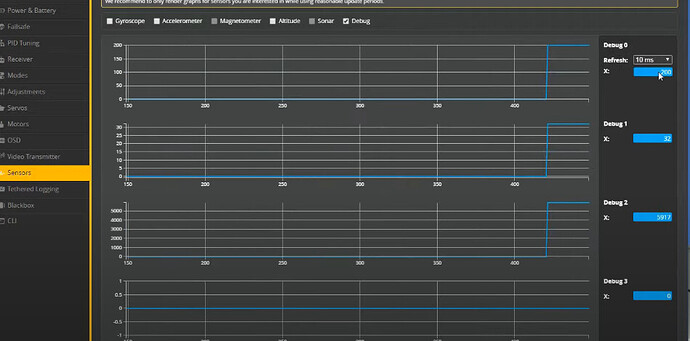
The value for Debug 0 can be interpreted using the table below. The value is calculated as SmartAudio Version * 100 + Device Mode. A device mode of 16 typically indicates that the VTX is "unlocked," meaning all frequencies and power levels are available.
| Debug Value | SmartAudio Version | Status |
| 100 | SA 1.0 | Locked |
| 116 | SA 1.0 | Unlocked |
| 200 | SA 2.0 | Locked |
| 216 | SA 2.0 | Unlocked |
| 300 | SA 2.1 | Locked |
| 316 | SA 2.1 | Unlocked |
Most non-TBS VTXs that support SmartAudio use version 2.0. Newer TBS hardware, such as the Pro32 and EVO series, utilize version 2.1. Knowing the precise version is paramount for selecting or building the correct VTX Table.
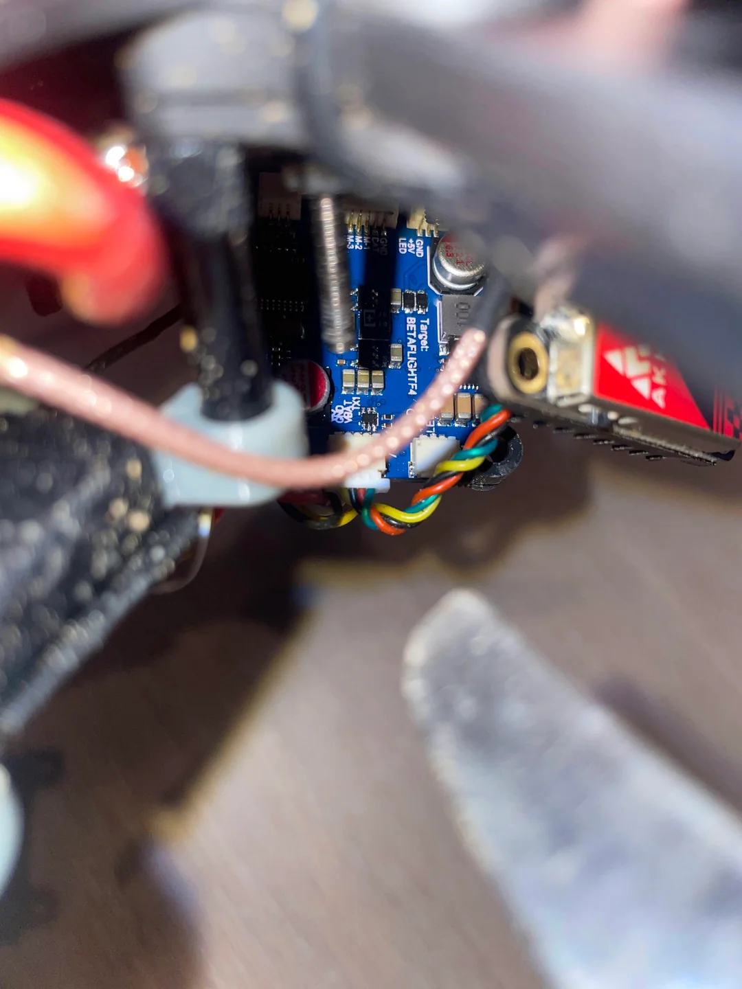
Section 2: The Groundwork: Physical Installation and Wiring
With the protocol version identified, the next phase is the physical installation. Correct wiring is fundamental, as no amount of software configuration can overcome a faulty connection.
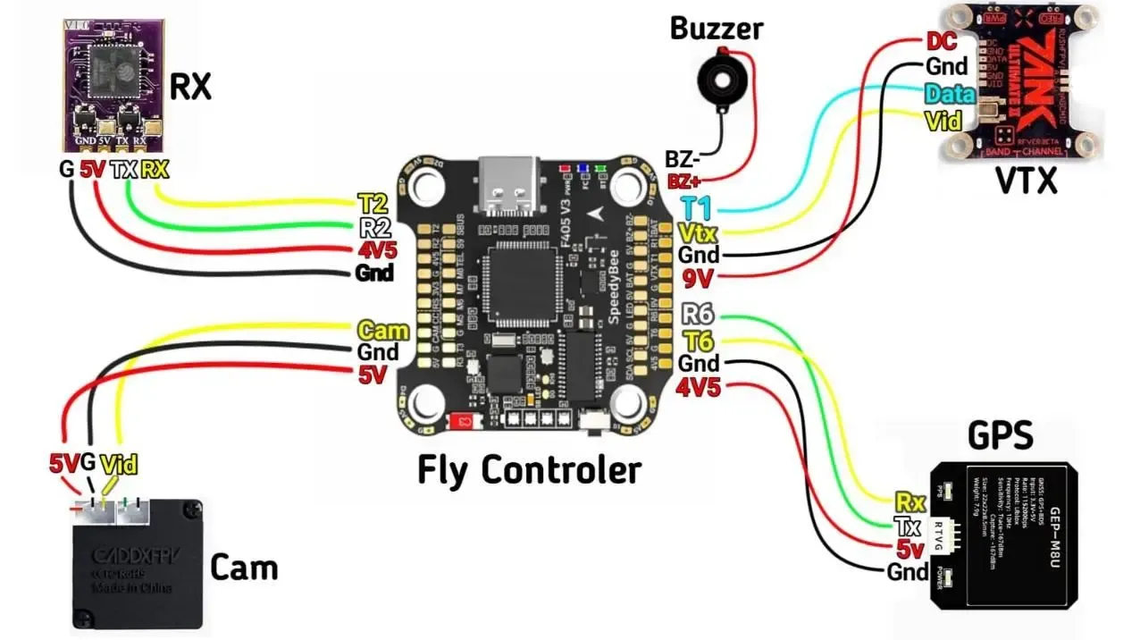
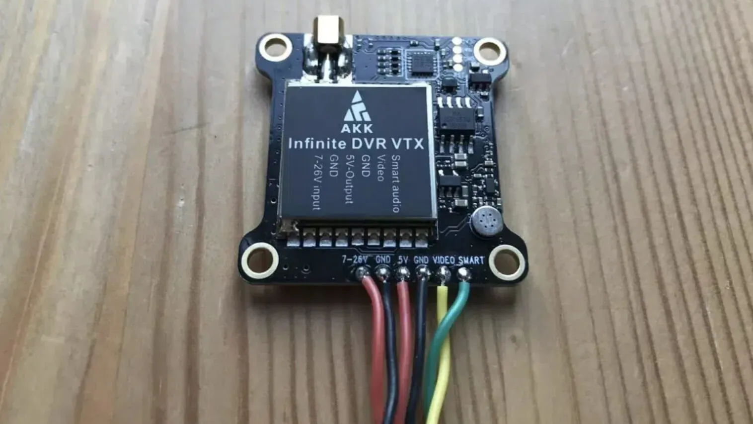
Wiring the SmartAudio Data Line
The SmartAudio protocol is a single-wire communication system. The golden rule of wiring is simple: Connect the VTX's SmartAudio data pad to a free TX (Transmit) pad on the flight controller. The TX pad of a UART is responsible for sending commands out from the flight controller to the VTX. The corresponding RX (Receive) pad on that same UART is not used and should be left empty. Connecting the SmartAudio wire to an RX pad is a common mistake that will result in a complete failure of communication.
Powering Your VTX and Camera
A clean and stable power supply is critical for a noise-free video feed. Most modern flight controllers provide dedicated, filtered power output pads labeled "9V" or "VBAT" for the VTX. Avoid using standard 5V pads unless your VTX explicitly requires it, as they may not provide sufficient current or filtering.
For the cleanest possible video signal, a best practice is to power the FPV camera directly from the VTX's own filtered 5V output, if available. This provides a form of double filtering, minimizing the risk of electrical noise appearing in your video feed.
Pre-Power-Up Safety Checks
Before applying LiPo power for the first time, two safety checks are non-negotiable:
- Antenna Connection: Always ensure a suitable 5.8GHz antenna is securely connected to the VTX. Powering a VTX without an antenna will cause reflected RF energy to destroy the amplifier, permanently damaging the VTX.
- Propeller Removal: For any bench testing or configuration, all propellers must be removed. This eliminates the risk of injury or damage from an accidental motor spin-up.
Section 3: Core Configuration in Betaflight 4.5+
Once the hardware is correctly installed, the focus shifts to configuring the Betaflight firmware to communicate with the VTX.
Flashing Betaflight 4.5: Start with a Clean Slate
When upgrading to a new major firmware version like Betaflight 4.5, it is strongly recommended to perform a Full Chip Erase during the flashing process. This option, available in the Firmware Flasher tab, wipes all old settings and prevents legacy configurations from causing unpredictable bugs. Starting from scratch is the most reliable method to ensure stability.
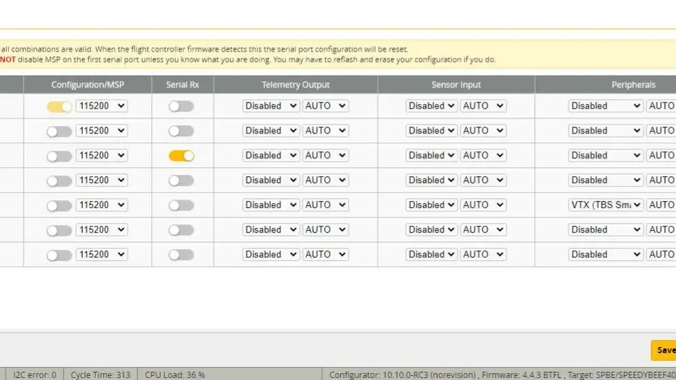
The Ports Tab: Assigning the Correct UART
The Ports tab tells the flight controller which physical port the VTX is connected to.
- Connect to your flight controller and navigate to the Ports tab.
- Identify the UART line that corresponds to the physical TX pad you used for wiring (e.g.,
TX3corresponds toUART3). - In the Peripherals column for that UART, select VTX (TBS SmartAudio) from the dropdown menu.
- Leave the Baud Rate at its default
AUTOsetting. - Click Save and Reboot.
The Configuration Tab: Enabling the OSD
To use the On-Screen Display for VTX control, the OSD feature must be globally enabled.
- Navigate to the Configuration tab.
- In the "Other Features" panel, ensure the OSD toggle switch is enabled (yellow).
- Click Save and Reboot.
Section 4: Mastering VTX Tables: The Heart of Modern VTX Control
The VTX Table is the central component of VTX control in modern Betaflight. It's a user-defined data structure that tells the firmware exactly which frequencies and power levels the connected VTX supports. Without a correctly configured VTX Table, SmartAudio will not function.
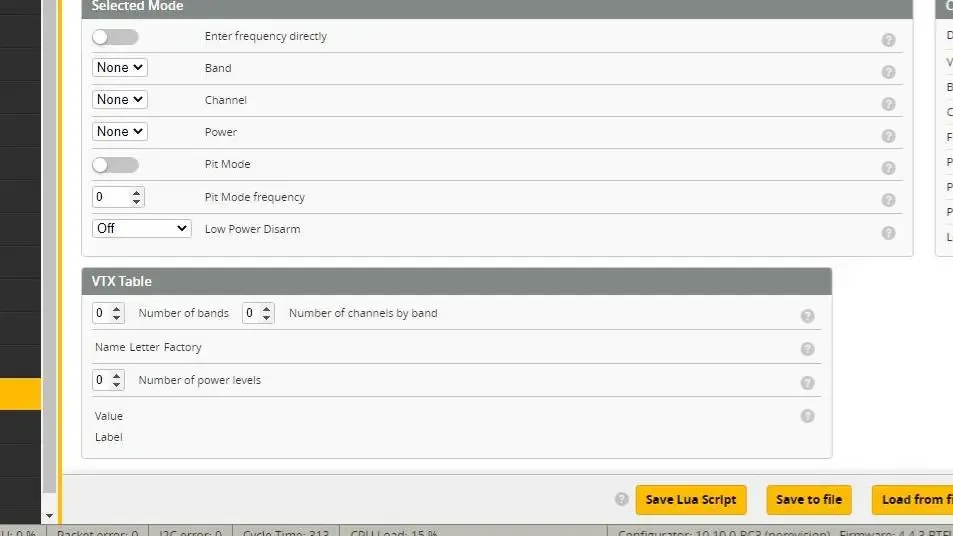
Deconstructing the VTX Table
The VTX Table, found in the Video Transmitter tab, consists of several key components:
- Bands & Channels: This defines the grid of available frequencies. Each band is given a descriptive Name (e.g.,
RACEBAND), a single Letter for the OSD (e.g.,R), and a list of up to eight frequencies in MHz. - The "Is Factory" Flag: This is a critically important setting.
- When Is Factory is enabled (checked), Betaflight sends the VTX a simple band and channel index (e.g., "Band 5, Channel 3"). The VTX then uses its own internal frequency map. The frequency values in the Betaflight VTX table are used only for display purposes in the OSD. Most SmartAudio VTXs operate in this mode.
- When Is Factory is disabled (unchecked), Betaflight sends the exact frequency value (e.g., 5732 MHz) to the VTX. This is required for VTXs like IRC Tramp that do not have extensive built-in frequency tables.
- Power Levels: This section defines the VTX's output power.
- Label: A user-friendly text string (up to 4 characters) displayed in the OSD, such as "25", "200", or "MAX".
- Value: This is the specific numerical code Betaflight sends to the VTX to command a power level. This value is not the power in milliwatts. It is a protocol-specific code, and using the wrong values for your SmartAudio version will cause power switching to fail. For example, SmartAudio 2.1 uses dBm values (e.g., 14 for 25mW), while older versions used different arbitrary values.
Finding and Loading Your VTX Table
Manually creating a VTX table is tedious and prone to error. Fortunately, pre-configured tables are widely available on the Betaflight Wiki. There are three primary methods to load one:
- Recommended: Load from File (.json): This is the most reliable method.
- Find the correct VTX table
.jsonfile for your VTX from trusted sources like the official Betaflight Wiki, manufacturer websites, or FPV community hubs. Pay attention to regional versions (USA, EU) to comply with local regulations. - In the Video Transmitter tab, click Load from file.
- Select the downloaded
.jsonfile. The tables should populate automatically. - Click Save.
- Find the correct VTX table
- Convenient: Use Presets: Some popular VTXs are included in Betaflight's built-in presets.
- Navigate to the Presets tab.
- In the "VTX" category, search for your VTX model.
- If found, select the preset, click Pick, then Save and Reboot.
- Advanced: Use the CLI: For tables provided as a block of text commands.
- Copy the entire block of
vtxtablecommands. - In the CLI tab, paste the commands into the input box and press Enter.
- Type
saveand press Enter.
- Copy the entire block of
Section 5: Verification and In-Flight Control
After the VTX table is loaded, the final step is to verify that the system is working correctly.
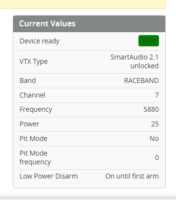
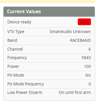
Confirming Success in the Video Transmitter Tab
The Video Transmitter tab is your primary diagnostic tool. After loading the VTX table and power cycling the drone (unplug and replug the LiPo), connect to the Configurator and observe the "Current Values" section.
The definitive indicator of a successful setup is the status Device Ready: True. This confirms that the flight controller is communicating with the VTX. If the status is Device Ready: False, there is a problem with your wiring, port configuration, or VTX table.
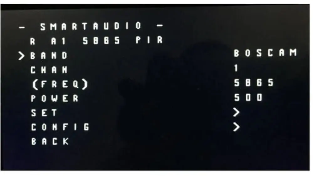
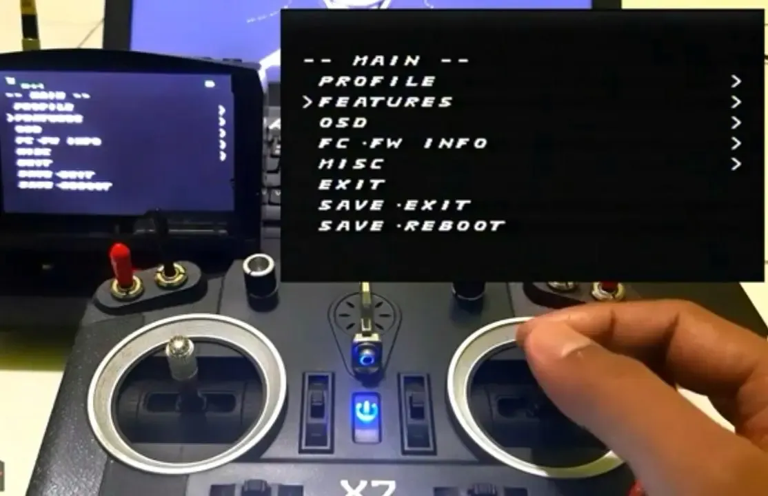
Accessing and Navigating the Betaflight OSD Menu
With the setup verified, you can now change VTX settings in the field using the OSD. To access the menu, the drone must be powered and disarmed.
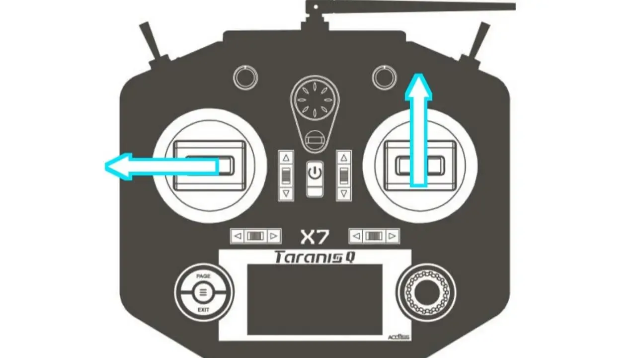
- Access Command (Mode 2):
- Throttle Stick: Center
- Yaw Stick (Left): Full Left
- Pitch Stick (Right): Full Forward
- Navigation:
- Pitch (Up/Down): Navigate through menu items.
- Roll (Right): Enter a submenu or confirm.
- Roll (Left): Go back.
- Changing VTX Settings:
- Navigate to FEATURES > VTX SA.
- Change the BAND, CHAN, and POWER values.
- Navigate to SET and press Roll Right.
- Confirm YES to apply the changes.
- Navigate back to the main menu and select SAVE & REBOOT.
Section 6: Advanced Troubleshooting for Betaflight 4.5+
Even with a careful setup, issues can arise. This section provides a systematic approach to diagnosing the most common SmartAudio problems.
The "Device Ready: False" Error
This is the most prevalent failure, indicating a complete breakdown in communication.
- Verify Physical Wiring: Double-check that the SmartAudio wire is securely soldered to a TX pad, not an RX pad. Inspect all solder joints.
- Verify Ports Tab: Confirm in the Ports tab that the correct UART has its Peripheral set to
VTX (TBS SmartAudio). - Verify VTX Table: Ensure a VTX table is loaded and that it is the correct one for the SmartAudio version you identified in Section 1. A version mismatch is a common, non-obvious cause of failure.
- Verify VTX Power: Ensure the VTX is receiving adequate and clean power.
Solving Firmware-Specific Bugs in BF 4.5.x
The Betaflight 4.5 development cycle introduced stricter compliance with the SmartAudio protocol. This can cause compatibility issues with older or non-compliant VTXs that worked on previous firmware versions. If your setup worked on Betaflight 4.4 but fails on 4.5, this is the likely cause.
The solution is to use a Custom Define, a special flag that alters the firmware's behavior.
- Go to the Firmware Flasher tab in Betaflight Configurator.
- Select your board target and the desired Betaflight 4.5.x version.
- In the "Build Configuration" section, find the "Custom Defines" input box.
- Type or paste
USE_NONCOMPLIANT_SMARTAUDIOinto this box. - Proceed to Load Firmware [Online] and Flash Firmware. This creates a custom build with a more lenient SmartAudio driver, restoring functionality for many affected VTXs.
Troubleshooting Table
| Symptom | Most Likely Cause(s) | Recommended Solution(s) |
| Device Ready: False or VTX Type: Undefined | 1. Incorrect wiring (SA on RX pad). 2. Incorrect UART in Ports tab. 3. VTX table is missing or incorrect. | 1. Verify SA wire is on a TX pad. 2. Double-check Ports tab. 3. Identify correct SA version (Section 1) and load the matching VTX table. |
| SmartAudio works on BF 4.4 but fails after updating to 4.5 | Firmware regression due to stricter protocol enforcement breaking compatibility with a non-compliant VTX. | In the Firmware Flasher, add the custom define USE_NONCOMPLIANT_SMARTAUDIO and re-flash the firmware. |
| Cannot change power levels, but can change channels. | The power values in the loaded VTX table are incorrect for the VTX's specific SmartAudio version. | Identify the correct SA version (Section 1). Find or create a VTX table with the correct power values for that version (e.g., dBm values for SA 2.1). |
| OSD tab is missing in Betaflight Configurator. | The OSD feature is disabled in the Configuration tab. | Go to the Configuration tab and enable the "OSD" toggle. |
| Video feed works, but OSD menu cannot be accessed. | 1. OSD feature disabled. 2. Incorrect stick command. 3. Video format (PAL/NTSC) mismatch. | 1. Enable OSD in Configuration tab.
2. Confirm stick command (Thr Center, Yaw Left, Pitch Up).
3. In the OSD tab, set Video Format to AUTO. |
Successfully configuring SmartAudio in Betaflight 4.5+ is a systematic process that hinges on precision. The critical path to a functional setup can be summarized in five key steps: Identify Version → Wire Correctly → Configure Ports → Load Correct Table → Verify.
The most common point of failure is overlooking the initial step of identifying the specific SmartAudio version and subsequently using a mismatched VTX Table. For users of Betaflight 4.5+, awareness of potential firmware regressions is also crucial, making the USE_NONCOMPLIANT_SMARTAUDIO custom define an indispensable tool. By following the diagnostic steps provided, pilots can systematically resolve nearly any issue they encounter and enjoy the full benefits of remote VTX control.