So you’re interested in FPV freestyle or racing but want a quad that’ll fit in your back pocket? We’ve got you covered! Read on for our complete build guide/log for our tiny kit! This build contains some small solder pads and some moderate amount of fiddling (as is the nature of micro builds), so is best suited for intermediate quad pilots to build. A beginner confident of their skills will probably be able to put this together just fine, though!
Where to Buy
Parts Section
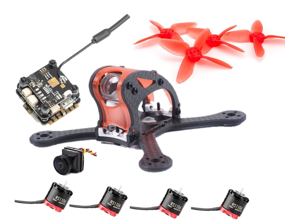
First off, here’s the list of parts we’ve
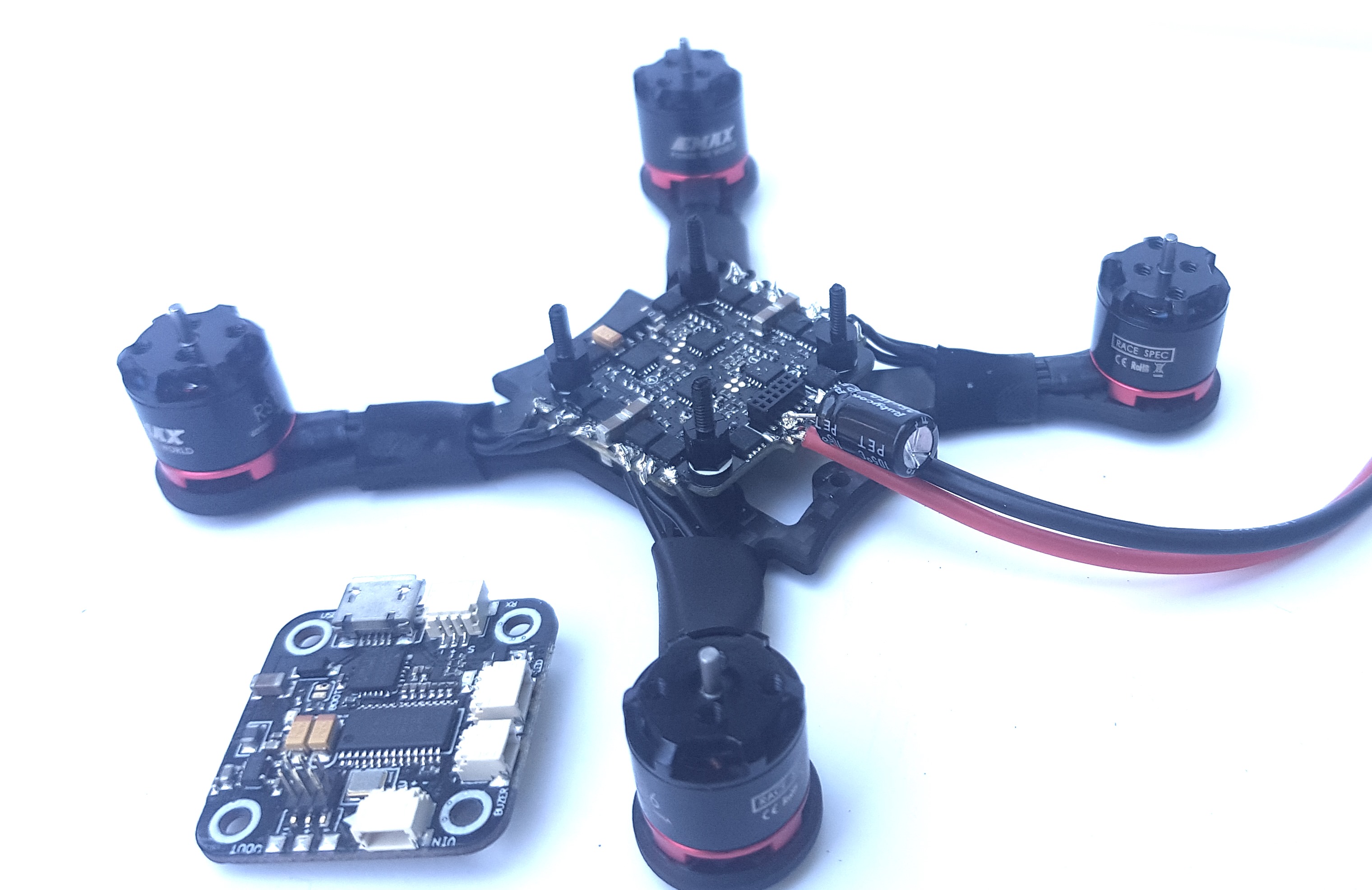
Spedix IS100 F4 Stack (VTX/FC/ESC C-c-c-Combo!)
This little 20×20 stack is fantastic. Small, compact, and relatively easy to work with – it’s the biggest time saver. The stack consists of 3 layers; VTX, FC and ESC. It all fits together via neat and tidy pins and pin headers for a clean finish at the end. We’ll need to cut down some of the included standoffs a tiny bit later for the best fit in the frame, and
The VTX:
The VTX is capable of 2 output powers, 25 and 100mW. Remember that in the UK only the 25mW setting is legal! This board sits on the very top of the stack, and the antenna is an ideal size for the GoFly frame, again helping to keep the overall finish nice and clean.
The FC:
The flight controller is an F4 board with all the features we’ll need in this micro sized build, and the beloved MPU6000 gyro. This gyro hits the sweet spot for quadcopters; sensitive enough to provide acute and accurate information to the processor but not so sensitive that it needs soft mounting to avoid twitchiness and burned out motors. this sits nicely in the middle of the stack and includes neat connectors for our RX and FPV camera – but some soldering is required on the board as part of the setup.
The ESC:
The last (bottom) layer of the stack is the 4 in 1 ESC. Rated for 20A and sporting BLHeli_S, this ESC is no slouch; it’ll easily handle out motors of choice.
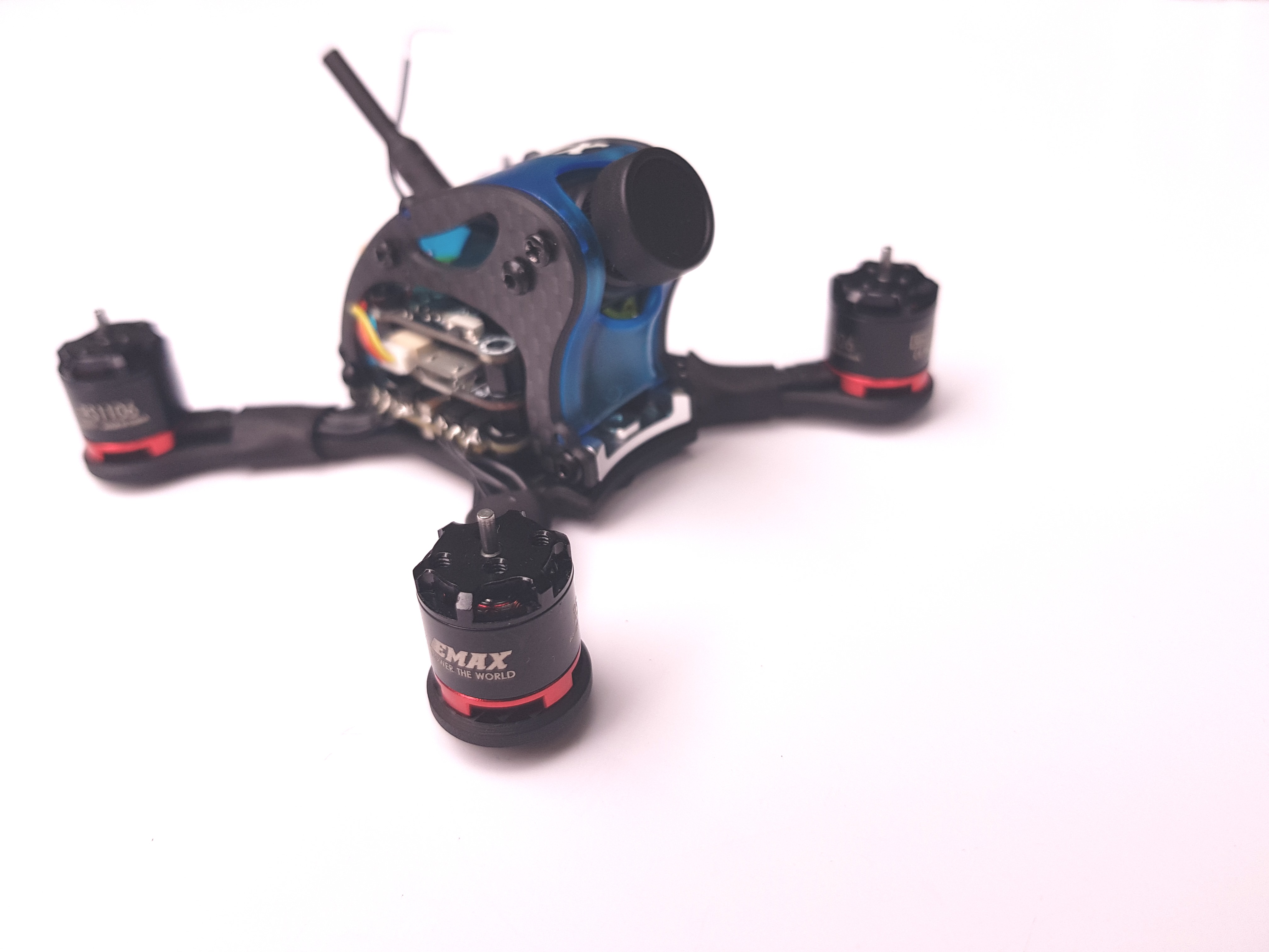
Emax 1106 6000kV Motors
These motors are crazy amounts of fun, and just crazy amounts of… Crazy! Capable up to 4S if you’re so inclined (though we don’t really recommend it – 3S is the sweet spot here) and filled to the brim with power, we just couldn’t say no. One of these on each corner of this tiny micro build gives you heaps of thrust and snappy control over the micro. Be warned – these motors can get hot even when well tuned! As long as you don’t overstep 80C and there’s no poor flight as a result, that’s perfectly normal here.
Caddx EOS1 Nano Camera
We saw 2 options for this build; the RunCam nano and Caddx EOS1. Ultimately, after trying them both out, we’ve settled with the Caddx. To be honest, we think it edges out the RunCam in most if not every way. The camera fits in the frame as if it were made around it, and the light response and picture quality are better on the Caddx. Not to say the RunCam isn’t a nice nano choice, of course!
FrSky XM Receiver (RX)
This receiver just seemed to be the perfect fit for this tiny build. Small, functional and cost effective, the XM binds to the popular Taranis radios with ease.
The Build (Quick Guide)
- Install the ESC to the bottom plate – use nylon screws and standoffs to secure. Ensure orientation is correct and tin the pads.
- Install the motors – you may wish to use heat shrink on the wires and loctite to secure the screws. Measure the wires to the ESC pads, and cut with an appropriate amount of slack. Solder these to the pads such that the wires do not cross one another. Ensure a secure connection is made.
- Solder the XT30 wires to your ESC, red to + and black to -.
- Install the Flight Controller, follow the preparation stems in the detailed build guide below (That is important!). Ensure orientation is correct and place on the standoffs. Secure in place with standoffs.
- Install the VTX, aligning the pins with the flight controller and securing to the standoffs with 2 nylon nuts on the will-be front side of the quad. Trim the excess exposed thread on all 4 standoffs with some wire cutters.
- Install the receiver. To do so, solder the receiver wire (with connector) to the receiver (after cutting to an appropriate length) such that the red wire goes to the + pad, black to – or GND pad , and yellow goes to the SBUS or signal pad. Press the connector in place into the flight controller. We recommend placing some heatshrink over the small receiver to isolate it.
- Mount the receiver with some 3M mounting tape or similar to the top of the VTX, being sure not to obscure the buttons on either the VTX or receiver. If you haven’t already, now is a good time to ensure your receiver is bound.
- Cut the camera wires to an appropriate length and solder to the corresponding cable provided with the flight stack. Place the camera into the black camera shroud provided with the frame, you may need to remove the lens to do so – be careful to avoid dust! Fix the camera to one of the frame’s side panels with a screw, and plug the camera cable in.
- Assemble the rest of the frame’s canopy around the camera.
- Bring the canopy over the base plate and components, and thread the VTX and receiver antennas through the frame’s canopy piece (there are appropriate sized cutouts).
- Secure the canopy assembly in place to the base plate, ensuring no wires are exposed beyond the sides of the frame and in danger od being damaged in a collision with the propellers.
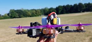
- Done! Enjoy our little UT-90 quad – we certainly have, that thing rips!
The Build! (Detailed guide)
Preparing the parts
Firstly, you’ll need to assemble the frame. As this is a micro build and the base plate is 1 piece, this is a simple process. You can choose to omit the plastic portion if you’d like, but, to be honest, we don’t know why you’d want to – it adds a certain level of protection and we like the splash of colour! You might get better cooling of your components without it, though. Leave out this black piece:
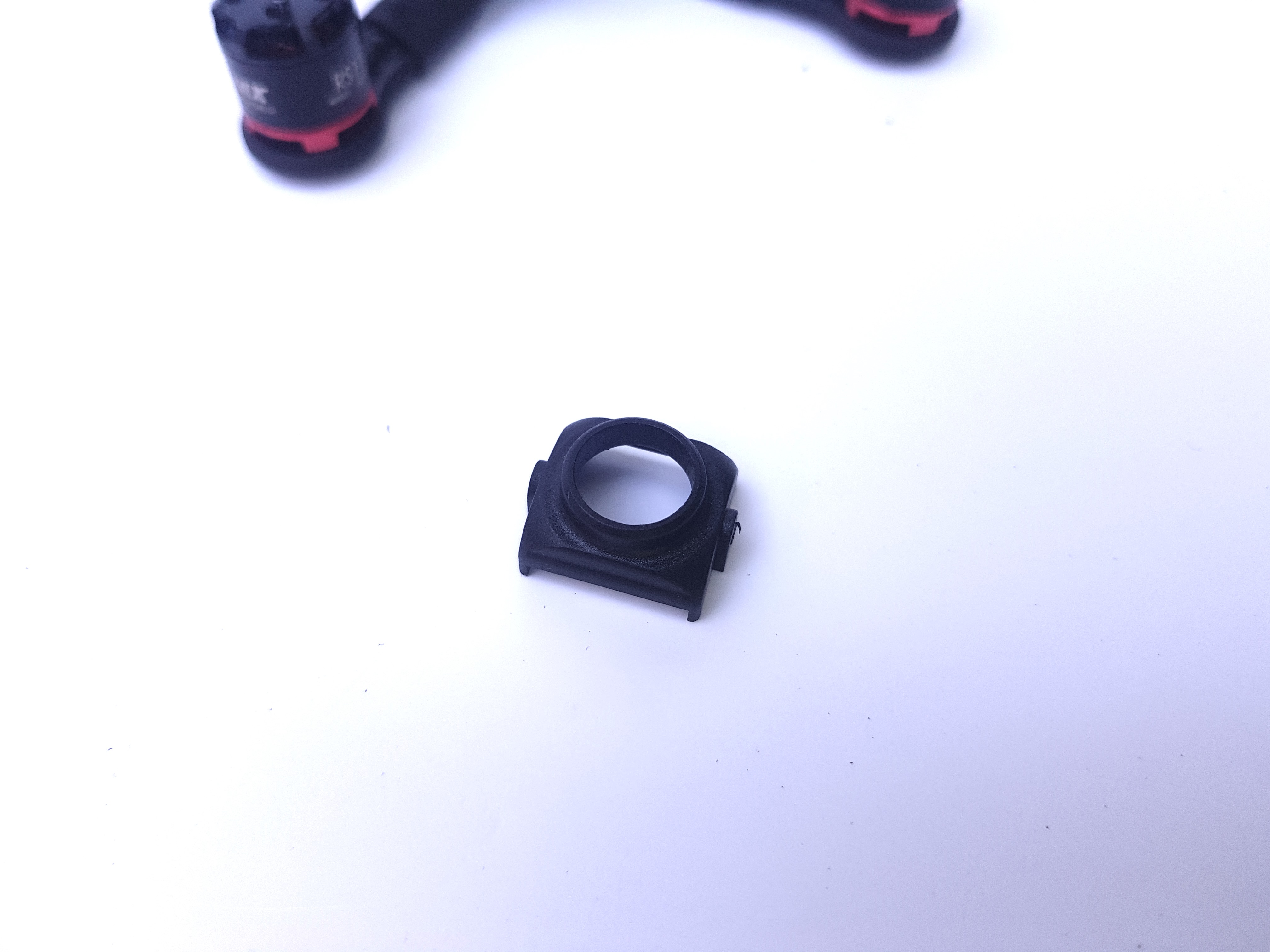
as we’ll need to fit the camera to it shortly. It’s also worth leaving the base (the arms) detached as we’ll need to install everything else before we put the canopy in place.
Once you’ve pieced the frame together we’ll move on to preparing the parts to be soldered up and connected.
Flight Controller Prep:
It’s not very well documented in the manual included for the FC – but you can’t simply stack it all together and have it work just like magic! There’s a couple of solder pads you’ll need to ‘jump’ together. Note that this guide is for the kit as standard, if you’re using different parts you’ll need to do a little bit of research to figure out what voltages your components take to avoid damaging them!
These pads are present so that you can select the voltage values that go out to your components. We’re going to need 5V for the stock VTX, 3.3 or 5V for the Caddx nano FPV camera (we’ve seen no difference in performance between either) and 5V for the receiver.
This is a simple process; add a tiny bit of solder bridging the pads together as shown in this image:
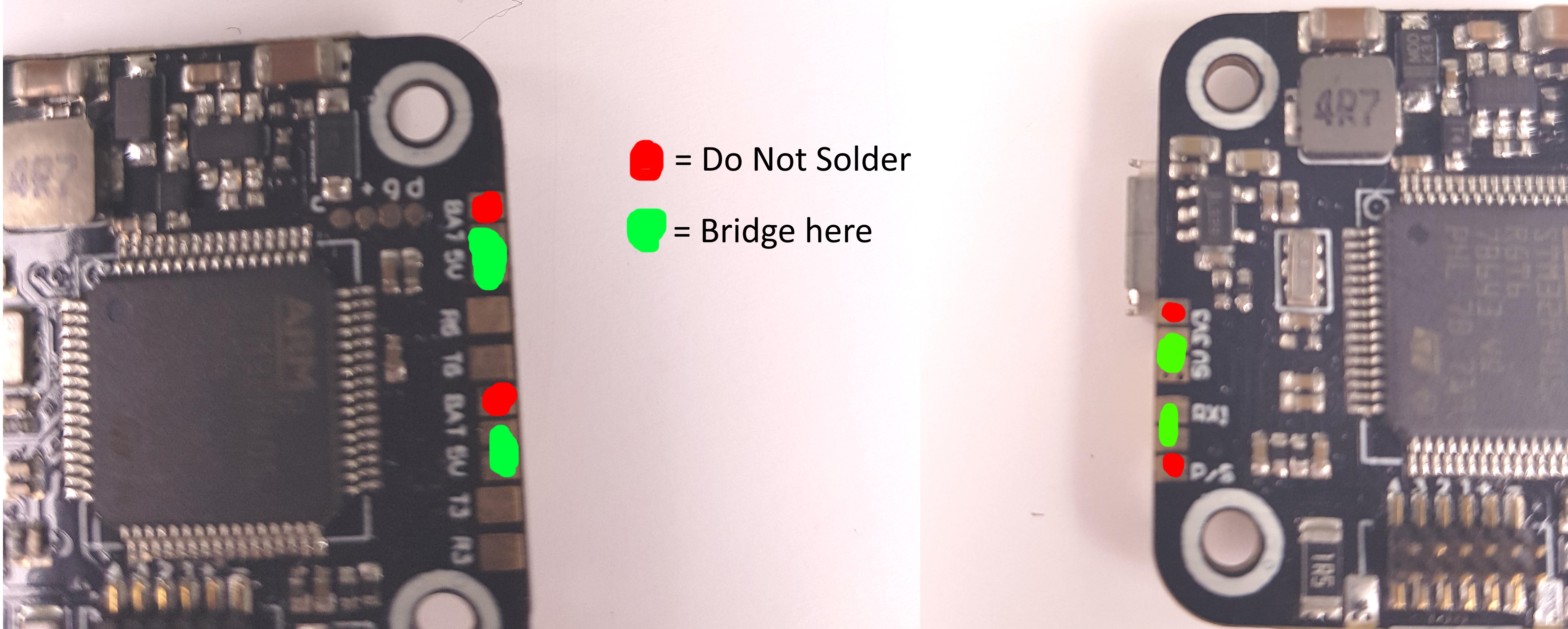
Then you should be all set on the FC!
Camera prep:
The camera comes with a connector attached that won’t work for us on this build. Luckily, the FC includes everything we’ll need to attach it correctly – and a quick bit of soldering will have us ready to go!
Firstly, cut the connector off of the camera. You can leave a short length of wire on the connector side if you think you can use it elsewhere or if, like us, you hoard random bits!
Next take this cable:
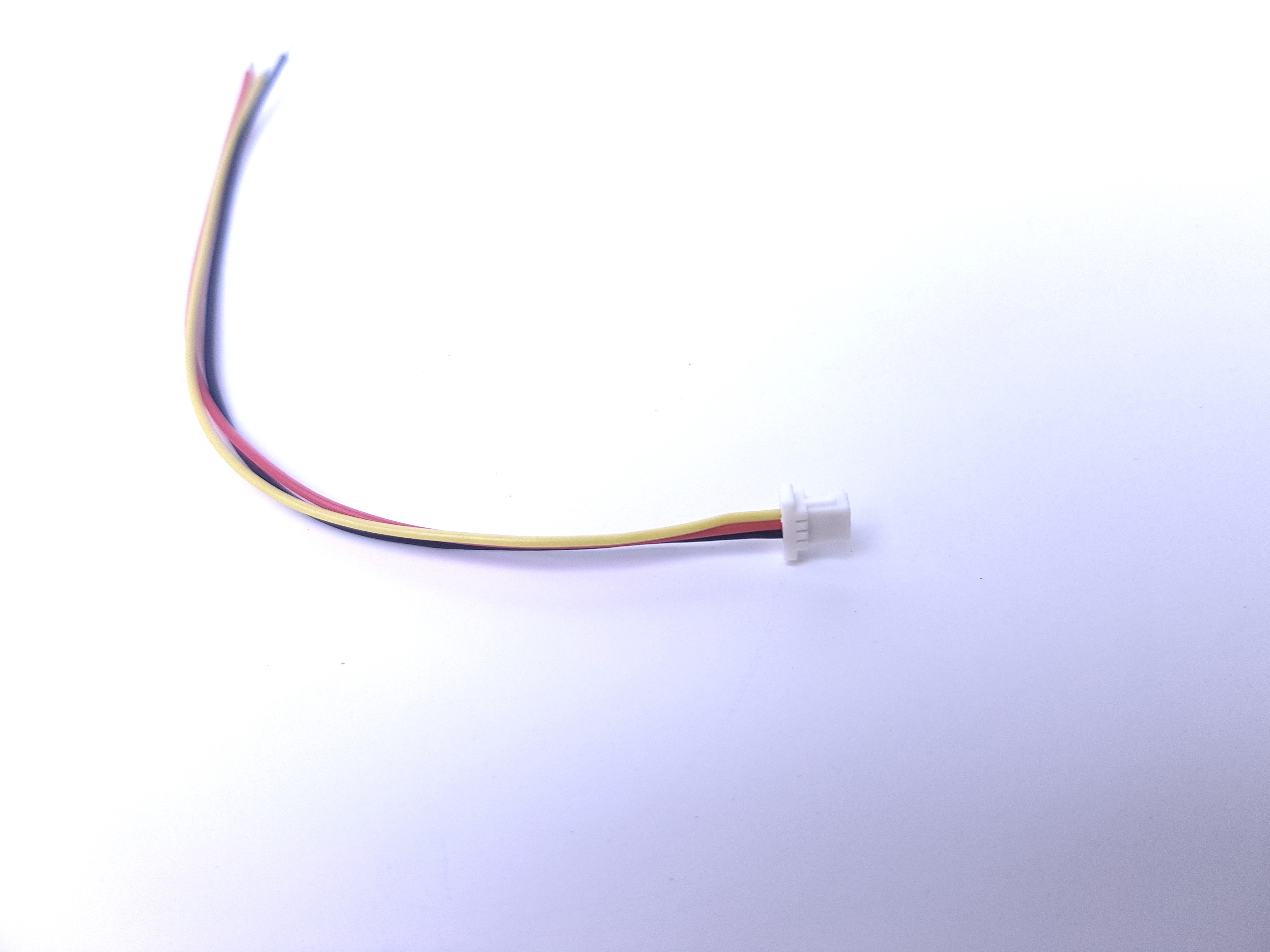
and cut it to a reasonable length. Remember, if you cut a cable too long it’ll likely be a faster remedy than if it’s too short! You may wish to cut down the cable on the camera side too. Then, tin the cables, slide some heat shrink over, simply match the colours together, and solder! Check that your joints are strong by giving the cables a slight tug. Shrink the heat shrink over the joints and the cable is ready to go!
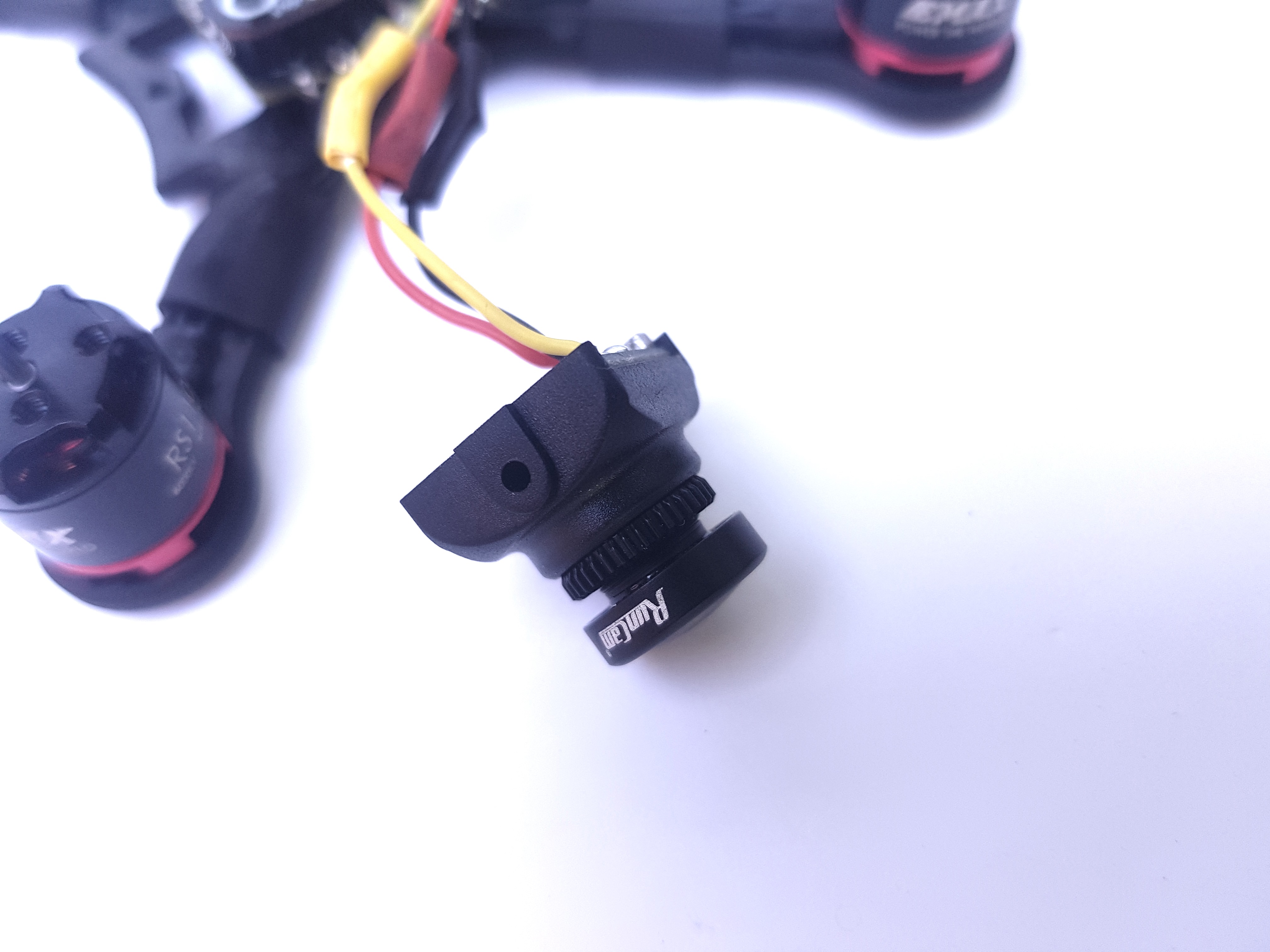
We’re not quite done with the camera – remember that black frame piece? We’ll install it here. The Caddx camera includes a small adjustment ring for focusing the lens properly. Conveniently, we’ve found that the space added between the sensor and the lens by the frame’s black camera shroud is practically ideal for focusing the image. Because of this, we’ll need to remove this focusing ring (see the images below). Be careful to do this installation fast and not let any dust settle on the sensor as you can end up with dots on your FPV feed!
Receiver Prep:
This one’s pretty simple. Measure out a sensible length of this cable:
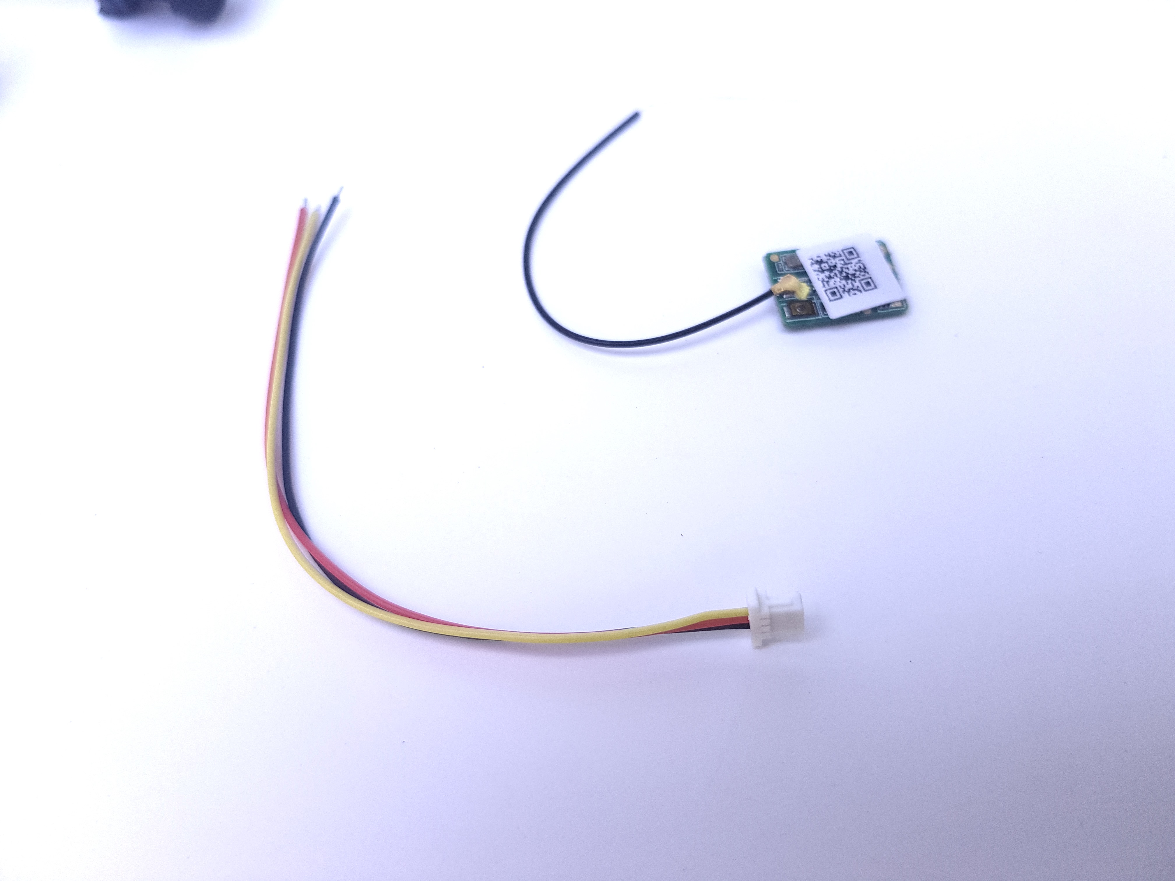
Make sure it’s the right one! There’s a few included with the flight stack. Cut and tin the wires, and tin the RX solder pads. Solder the 3 wires to the RX as shown in the image here:
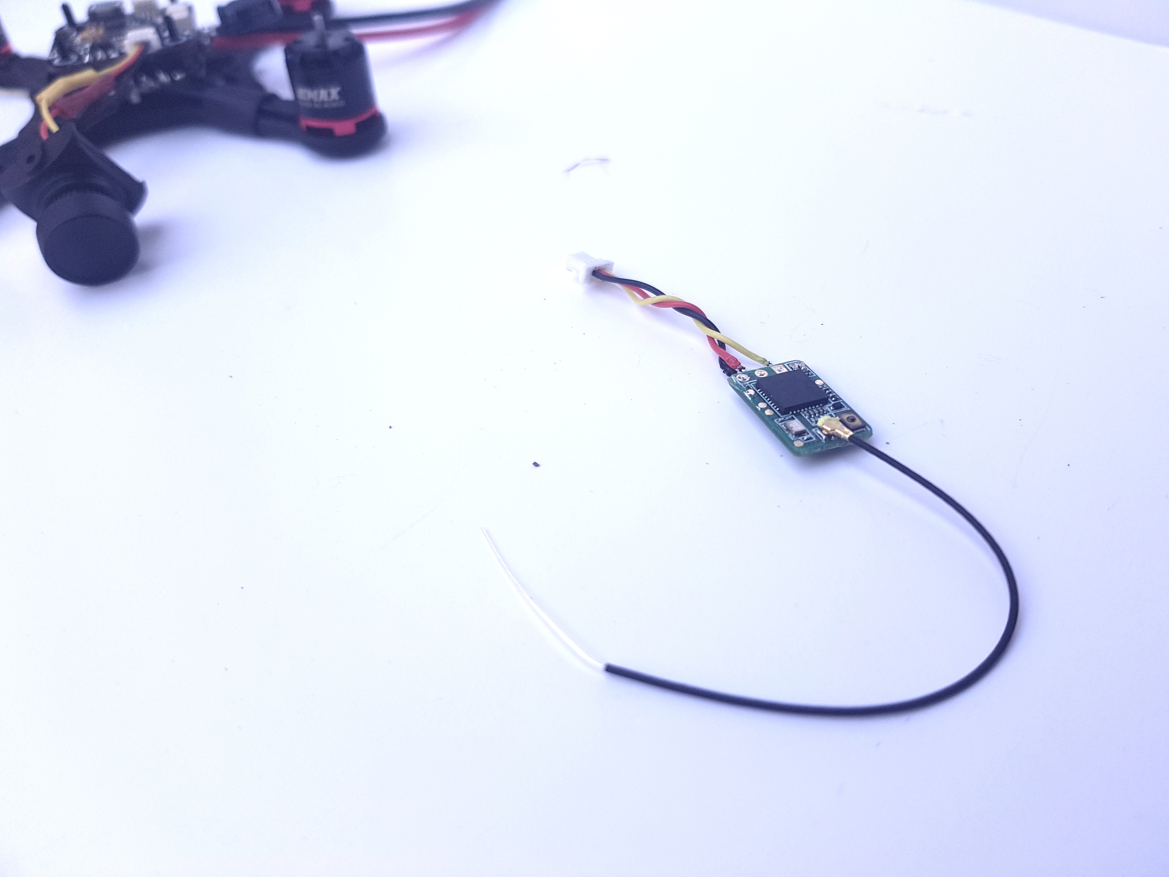
Then you can set it aside for later!
Motor Prep:
Measure out the motor wires to this length against the frame, making sure you’ve got enough room to connect to the ESC without too much excess wire left on the quad. Ideally, you want clean runs with an even curve in the wires where they bend to reach the ESC, without putting any strain on the wires when the motors are bolted down. Strip a couple of mm off of the end of each motor wire, and tin the exposed ends with a soldering iron.
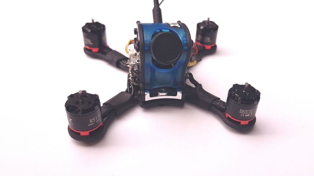
Installing the ESC and motors
The next steps, provided all of the preparation was done, should be relatively simple. Note the orientation the ESC needs to be installed so that the flight controller in the stack will be pointing forwards. Install 4 nylon screws through the base of the frame, and on the other side, screw 4 nylon nuts in place. Next, slide the ESC over these standoffs such that the orientation is appropriate for the flight controller to face forwards once installed, and screw the nylon standoffs in place to hold the ESC down.
With the ESC in place, and secured, now is a good time to tin the pads. Tin each motor pad (12 in total) and the battery pads. Be sure not to bridge the solder at any point, and also be sure not to let any of the solder touch the frame to avoid damage or other issues. ou may need to remove and reinstall certain standoffs to make manoeuvring your soldering iron around the ESC a little easier.
Once this is done, install each of the 4 motors onto the frame. Make sure they’re oriented in such a way that the wires will run down the arms of the frame towards the ESC. It’s recommended to use some loctite on the motor screws, though, not too much! If you wish, you can cut some heatshrink as I have to go over the arms and motor wires in an effort to achieve a cleaner look, and add some minor protection to the wires. This will need to be done before you put the motors in place, otherwise you likely won’t be able to get the heatshrink over the motor.
Match up each wire to a tinned motor pad. Your motor pads are in sets of 3, as long as the middle motor wire goes to the middle motor pad in each set, the orientation of the outer wires (left to left, right to right, or mixed e.g. left to right and right to left) won’t matter as this can be corrected in software later on. The cleanest visual install, in my opinion, is when all 4 motors match the left wire to the left pad, and the right wire to the right pad. Solder these in place.
If you installed heatshrink earlier, now is the time to shrink it in place (after soldering the wires to each pad).
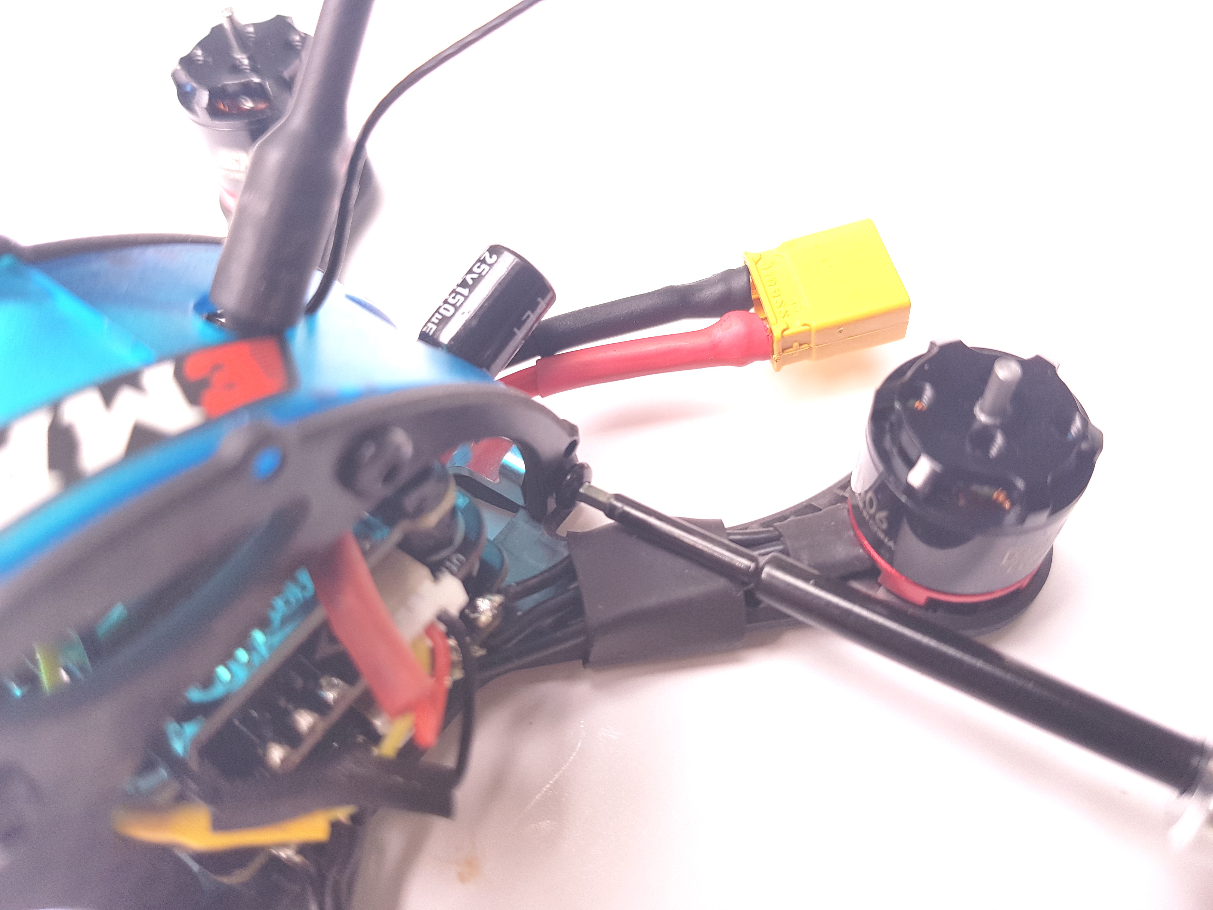
Solder your XT-30 connector to the thicker wires provided in the kit, making sure the + and – pins match your wires (+ to red, – to black). Place some heatshrink over these connections and shrink it in place to protect the joints.
Cut the wires to an appropriate length and strip and tin the ends. Solder these to your ESC, again, matching + to + and – to -, otherwise you are likely to cause significant damage.
You may wish to install the included capacitor. WE haven’t found it necessary – though it may help to reduce noise should you find you have any in your video feed. One side of the capacitor is marked with a -. Make sure this side is soldered to the – pad on your ESC, and the other leg is soldered to the + pad.
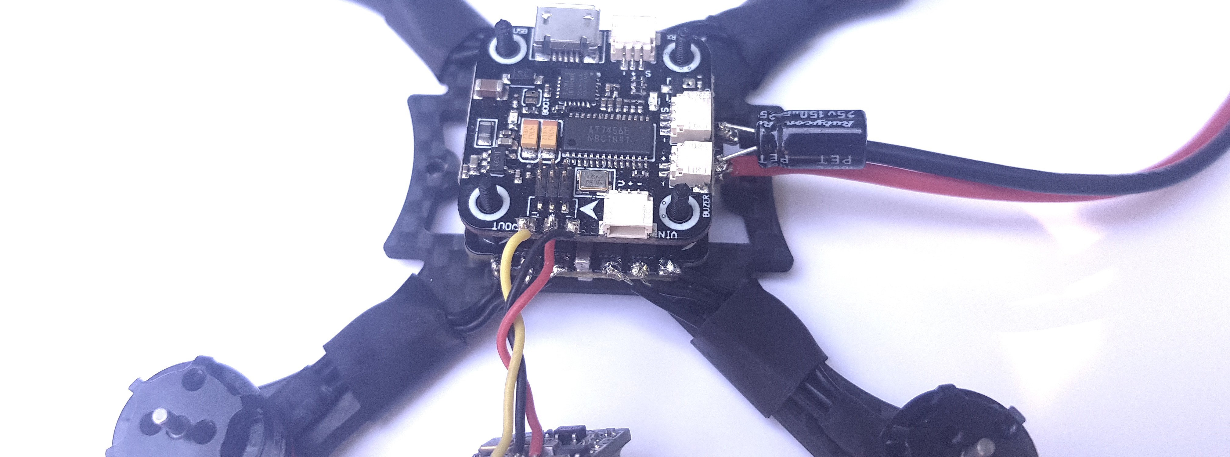
Installing the Flight Controller
This part is simple. With the flight controller jumpers set appropriately as per the earlier preperation instructions, you can simply place the flight controller on top of the ESC such that the 4 standoffs slide easily through the FC’s mounting holes, and the pins on the FC align with the recipient pin header on the ESC. Gently press this in place so that all the pins connect securely, and then use some more standoffs to screw the FC in place.
Installing the Receiver and VTX
Much like the flight controller onto the ESC, orient the VTX correctly so that the pins align with the flight controller and gently install in place. Then use two nylon nuts on the front side of the VTX to secure it in place. Trim the exposed threads above the nylon nuts at the front and above the VTX at the back to ensure the frame will fit over correctly.
If you followed the preparation steps earlier, installing the receiver should be as simple as plugging the cable into the flight controller and mounting it to your stack with some double-sided mounting tape or foam.
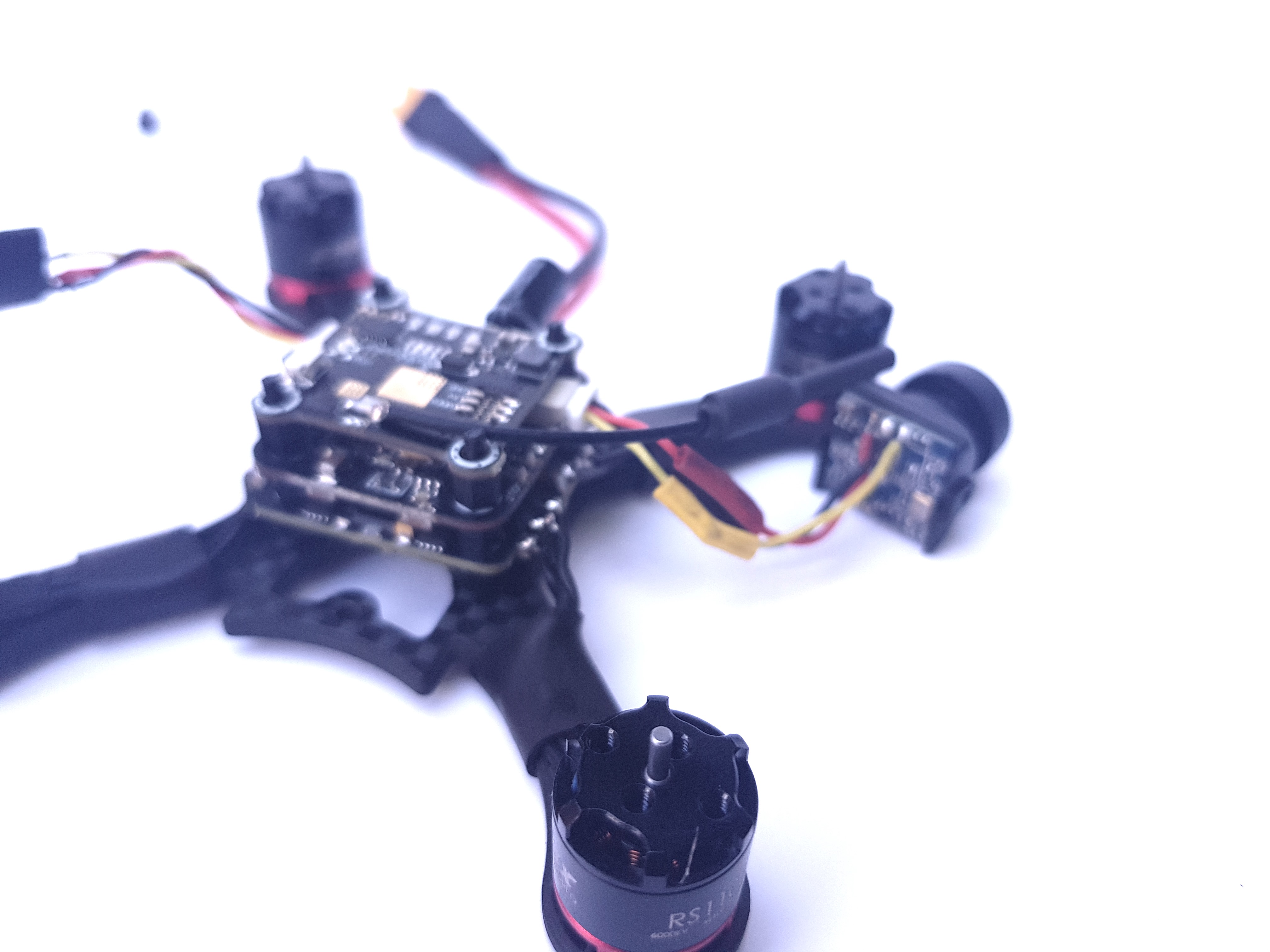
Installing the Camera
Take the top portion of the frame (the blue ‘canopy piece’ and the side panels) and remove one side. Place the camera (remember at this point it should be installed into the black piece included with the frame) against the side panel that is still attached to the canopy and screw it into place, be sure not to use screws hat are too long as you risk damaging the camera.
Re install the remaining side panel, and screw the other side of the camera into place.
Finally, for the camera, press the connector into the FC.
All of the functioning pieces of our kit are now together, and you should be able to connect a battery to check that everything boots up correctly! We recommend this step to make troubleshooting easier should an issue occur.
Finishing off – the last pieces!
Now that everything has been checked and working, you can set you VTX channel and power using the button on top to your preference. Also, you should bind your receiver at this point, unless you’ve already done so.
Carefully bring the canopy over the bottom plate, covering the stack. You should be able to slide the receiver and VTX antennas through the canopy piece.
After this, you should be able to screw everything in place to complete the build!
You can use small battery straps or rubber bands to secure a battery to the quad for flying, a quick google search will bring a number of solutions for this.
I went with a combination of some old runcam battery strap we had laying around and some rubber bands to secure the battery, and it’s lasted me ever since. I fly with 850mah 3S 75C Tattu batteries available here: link
Running the betaflight stock PID’s (or Emax’s babyhawk PID’s) this thing flies surprisingly well, I had a hard time discerning between this build and my “full sized” 5″ quad that I fly on a daily basis, and the battery life is superb – while maybe not best in class, the performance/battery life ratio is something we really think we nailed down with this little build – we’ve had an absolute blast with it!