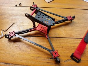
As a beginner, it can be quite confusing when it comes to connecting all of your FPV quadcopter electronics for the first time. To make things worse some things in the hobby don’t always come with particularly great instructions. However, as you build more drones you will notice that there are alot of common ways to connect everything, even if the electronics are different. So rather than writing another guide specific to some flight controller this guide will teach you the basic concepts to allow you to figure out how to hook just about anything FPV related. In this first part of the series, we will be talking about Motors and ESC.
Connecting your Motors and ESC
Connecting your motors and ESC is something you need to do on every quadcopter build, and fortunately, it is quite straightforward. During most new builds, once the frame is assembled the first soldering task is soldering the motors to your ESC. This is then followed by soldering the ESC to your power distribution board (PDB) and Flight Controller (FC). Before we continue, below is a basic example of the connectors you would usually find on your ESC.

Motors to ESC
To connect your motors to your ESC you just need to solder the 3 motor wires to the motor solder pads on the one side of the ESC. They will be 3 tabs close to each other and are usually the biggest ones on an ESC. An example connection is shown in the image below.

- It is a good idea to first mount your motor to your frame, and measure how long the motor wires need to be to reach your ESC, and then cut them down to size to ensure a neat build. You don’t want to have wires flopping around that can get caught in a propeller.
- Another tip is to try and make sure the motor wire order going to each of your ESC is consistent. So the first wire from your motor goes to the first connection on your ESC, and the middle wire from your motor goes to the middle tab on your ESC. Doing this makes configuring your quadcopter much easier later on. If you connect it wrong its not a big deal as the motor will just spin the wrong way around and you need to change a setting to reverse it via your ESC configuration software.
ESC to Flight Controller
In order for the ESC to receive inputs they need to be connected to your flight controller. Each flight controller has a number of motor output connections, usually labelled motor 1, motor 2.. or PWM1, PWM2, sometimes S1, S2 or M1, M2 etc… You can find these by looking at your flight controller for labels, or the manual for your flight controller.
To connect an ESC to your flight controller you need two wires per ESC. A signal and ground. Using the ground wire is not absolutely necessary but is highly recommended as its best practice to ensure all the electronic devices have a common ground, so if you can just connect it. The order in which you connect the ESC is important. You will need to connect motor 1 of your drone to motor connector 1, and motor 2 to connection 2. Your flight controller software manual will let you know what order you need to use.

As an example Betaflight requires the rear right motor to be motor 1, so you would connect this Motor/ESC to the motor connection 1 on your flight controller. Similarly motor 4 (front left motor) would need to connect the motor connector 4 on your flight controller.
Let’s start to look at the flight controller below. It has nicely labelled connections. Each of the 4 ESC connectors are located on the edges of the board labelled S1, S2, S3 and S4. You would solder the signal wire form each of your ESC to the corresponding pad. Next to each one is a ground pad that you would solder the ESC signal ground wire to.

The location and naming convention for flight controllers are varied. As another example, the omnibus F4 V5 flight controller below has all of the motor connections in a row. But the concept is still the same, you would connect ESC 1, to PWM1 on the flight controller etc…

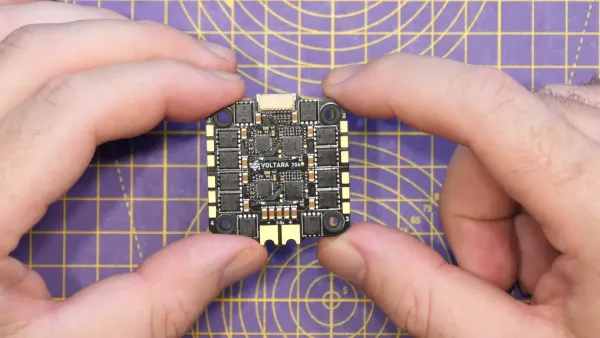
What about a 4in1 ESC
You also get 4in1 ESC, and as the name suggests is a single board with 4 ESC built into it. The logic is exactly the same as with 4x individual ESC as there are 4 sets of motor soldering tabs and 4 sets of ESC signal connections. A 4in1 ESC is more convenient to use as there is less messy wiring as the powering of each ESC is done internally on the board.

As you can see in the diagram above for a typhoon ESC, there are 4 groups of 3 motor soldering tabs, so you would solder each motor to each group. To connect the ESC to your flight controller, most 4in1 ESC uses a connector to make wiring neater. The pinout labelling for the connector is usually included with the manual. In this example, the first 4 pins on the connector are for motors 4-1. NC stands for not connected. GND is for the ground connection to your flight controller. TLM is for ESC telemetry. VBAT will output the input battery voltage and connects to VBAT on your flight controller. This allows the flight controller to monitor the battery voltage.
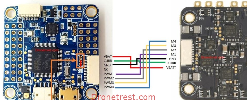
As mentioned, most of the time when using a 4in1 ESC they will include a connector that plugs into your FC. This is shown below where the connector of the 4in1 ESC will plug into the 4in1 ESC connector on the flight controller. It is important again to note that there is no industry standard for the type of connector, or connection order so you should always check with the manual. But again the idea of connecting ESC 1 to FC connector 1 (PWM1) and 2 to 2 is still the same. The VBATT, CURR connectors are features from this 4in1 ESC that let the FC read your battery voltage and current used by the motors.
ESC Telemetry
Any Questions?
I hope that this article has helped but if not please ask a question over on dronetrest so I can try help. I will also appreciate any feedback to help make this article even better as its kind of a hard thing to explain in a simple way. Otherwise be sure to check out our other quadcopter connection guides to continue learning!