Most RC GPS setups assume a flight controller sits in the middle, doing the usual serial babysitting. ELRS 4.0 breaks that assumption and lets a receiver ingest GPS directly, which means a car, boat, or plain servo-driven plane can now report location without extra avionics.
That is the trick here: plug a GPS into an ExpressLRS receiver, push telemetry back to the radio, and use that data for coordinates, QR codes, or live mapping. No flight controller, no Betaflight, no mystery black box pretending to be mandatory.
What changed in ELRS 4.0
This works because ExpressLRS 4.0 added support for directly attached GPS inputs on the receiver. If the gear still runs ELRS 3.x, this feature does not exist, and no amount of optimism will change that.
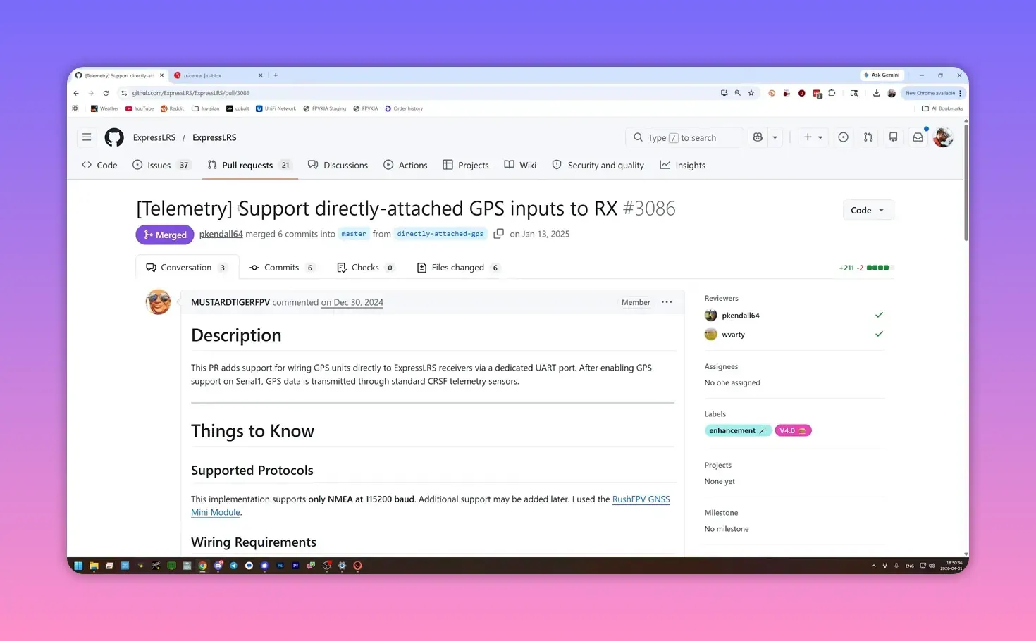
Both ends need ELRS 4.0 or newer: the receiver and the transmitter module or radio. If a firmware update has been waiting for a reason, this is at least a decent one.
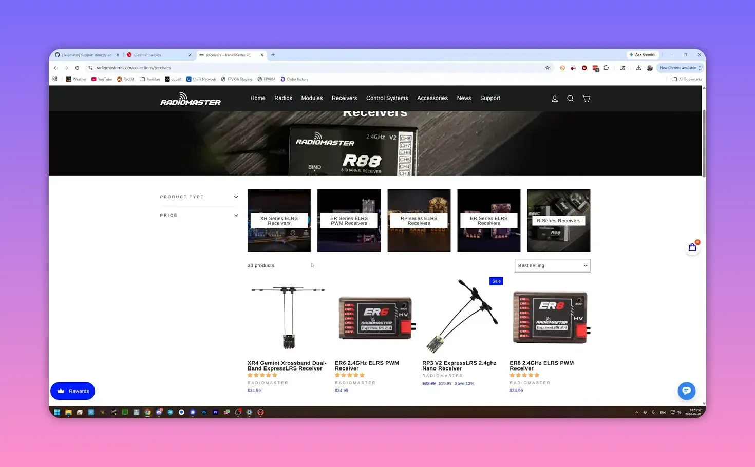
Which receiver makes sense
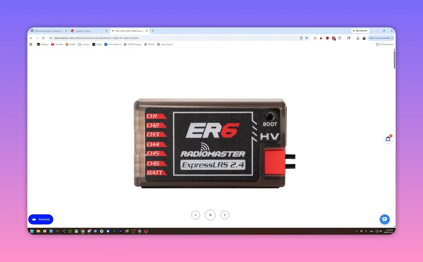
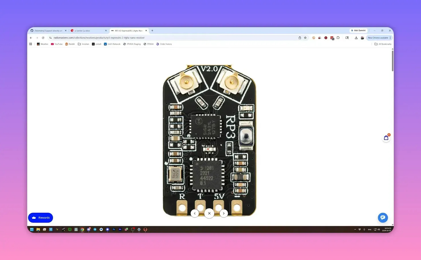
The most common target is a PWM receiver. That fits the vehicles that usually lack flight controllers anyway: RC cars, boats, and old-school planes with servos and a receiver doing all the work.
With a PWM receiver, one of the output pins gets repurposed as a serial port for the GPS. That means one servo output disappears. A six-channel receiver with six servos leaves no spare channel, so either lose a function or buy a receiver with more outputs.
Serial-based receivers can also do the job, but with a catch. If the receiver only has one TX/RX pair, using it for GPS means it cannot also talk to a flight controller for control data.
That makes a single-UART serial receiver more suitable for a standalone tracker than a normal controlled model. Some receivers, like the XR4, include a second UART, which neatly avoids that compromise.
Joshua Bardwell used an ER3CI for the demo. It is not the ideal real-world choice because burning one of three channels on GPS leaves exactly two channels. Great for proving a point, less great for creature comforts.
Configure the receiver over Wi-Fi
First, put the receiver into Wi-Fi mode. That can be done from the ExpressLRS Lua script with Enable RX Wi-Fi, or by powering the receiver for about a minute without a connection and letting it enter Wi-Fi mode by itself.
Connect to the receiver’s Wi-Fi network. The default network is the ExpressLRS RX access point, and the default password is expresslrs in lowercase.
Then open a browser and go to 10.0.0.1. That loads the ExpressLRS web interface for the receiver.
Turn PWM outputs into serial TX/RX
In the Connections section, pick one output and set it to Serial TX. The paired pin will automatically become Serial RX.
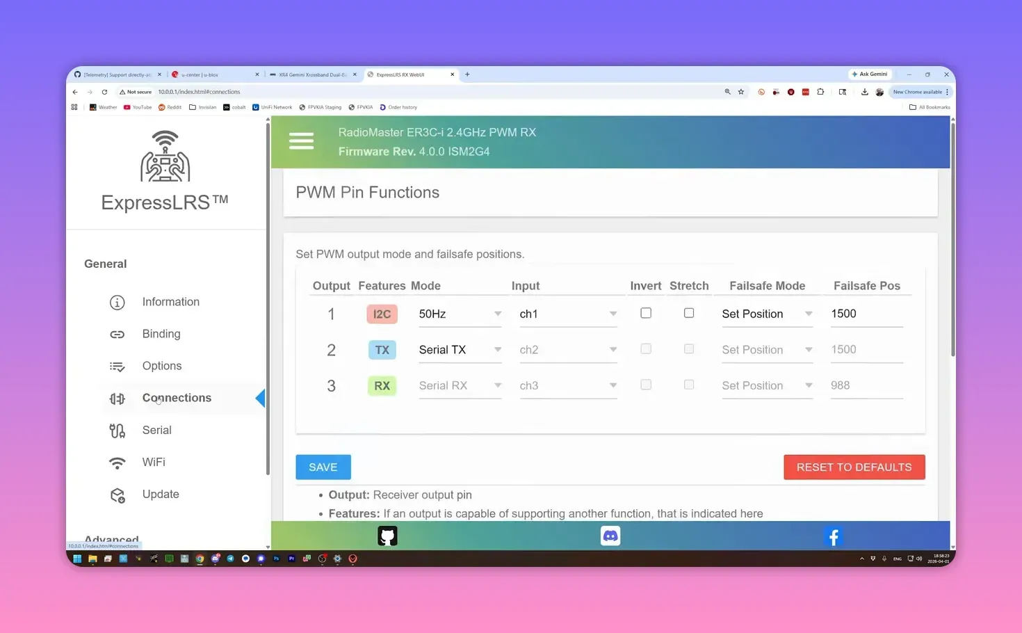
Not every receiver maps serial to every pin, so the exact options may vary. The important part is to note which physical pin becomes Serial RX, because the GPS transmit line must land there later.
Set the UART protocol to GPS
Next, open the Serial section and set the relevant UART protocol to GPS. On receivers with multiple UARTs, one can stay on Crossfire for normal duties while another handles GPS.
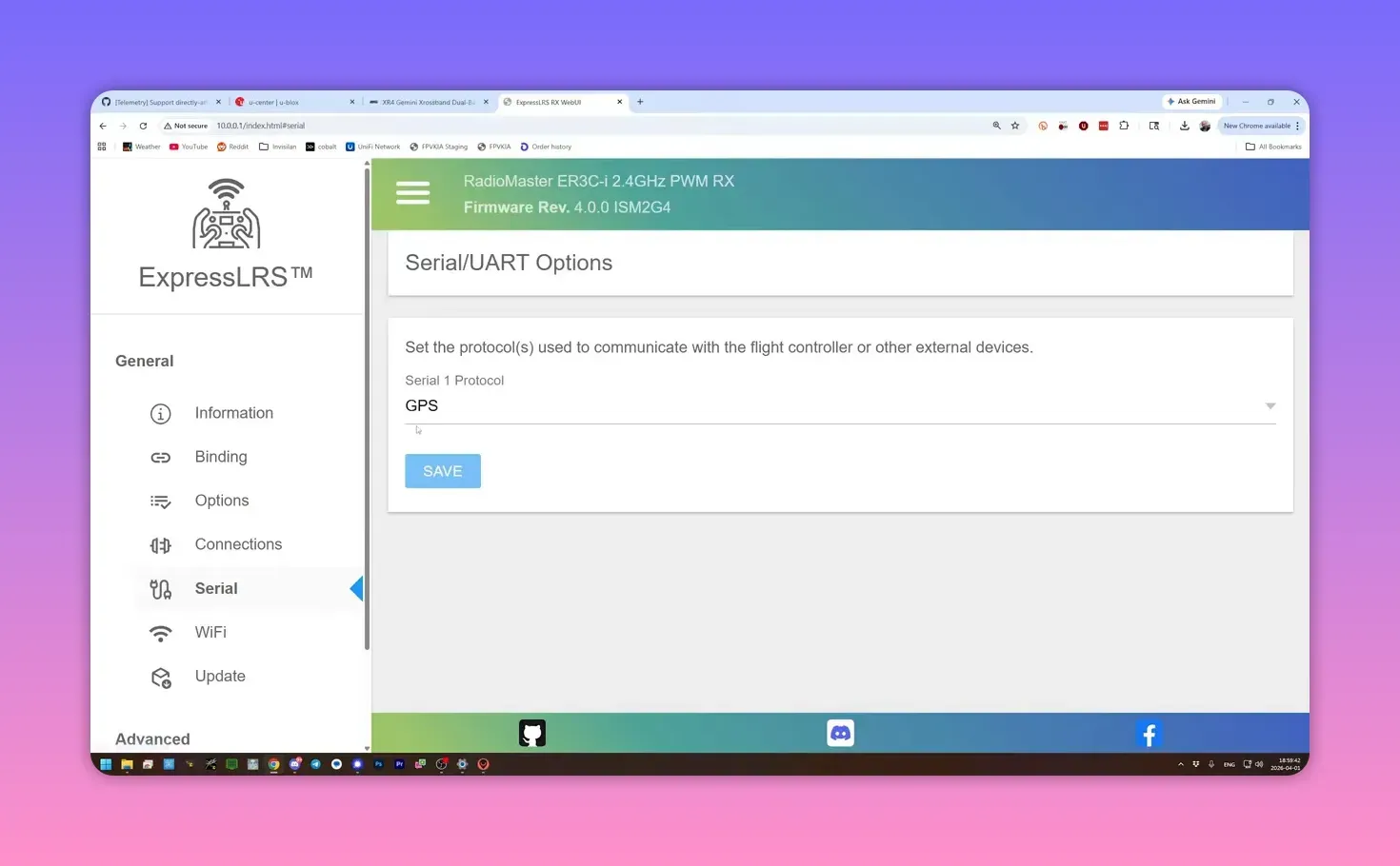
The goal is simple: one UART must speak GPS, and the pins assigned in the Connections page must match that UART. Save the settings, and the receiver is ready for wiring.
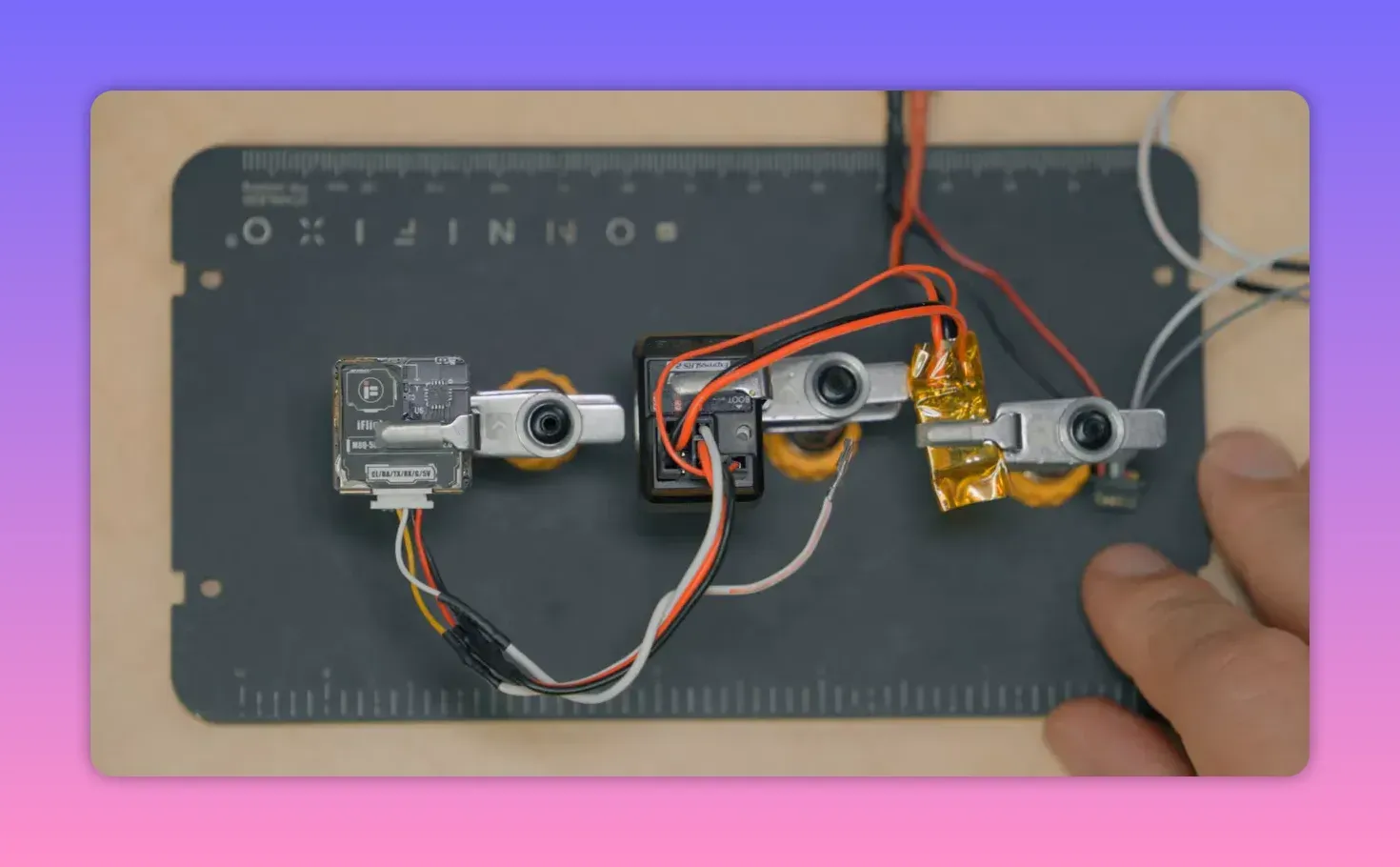
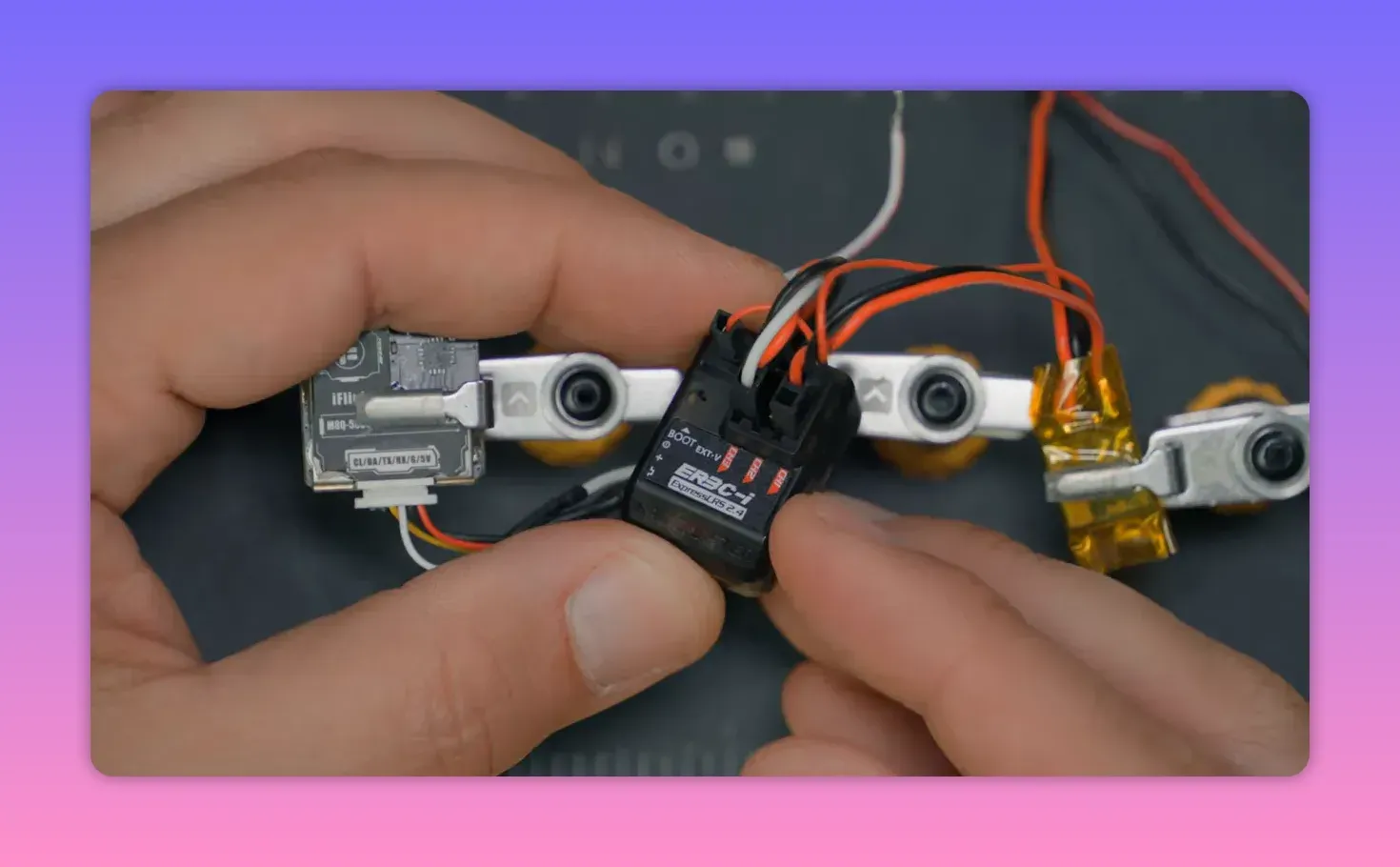
Wire the GPS to the receiver
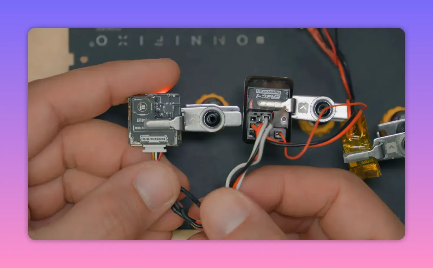
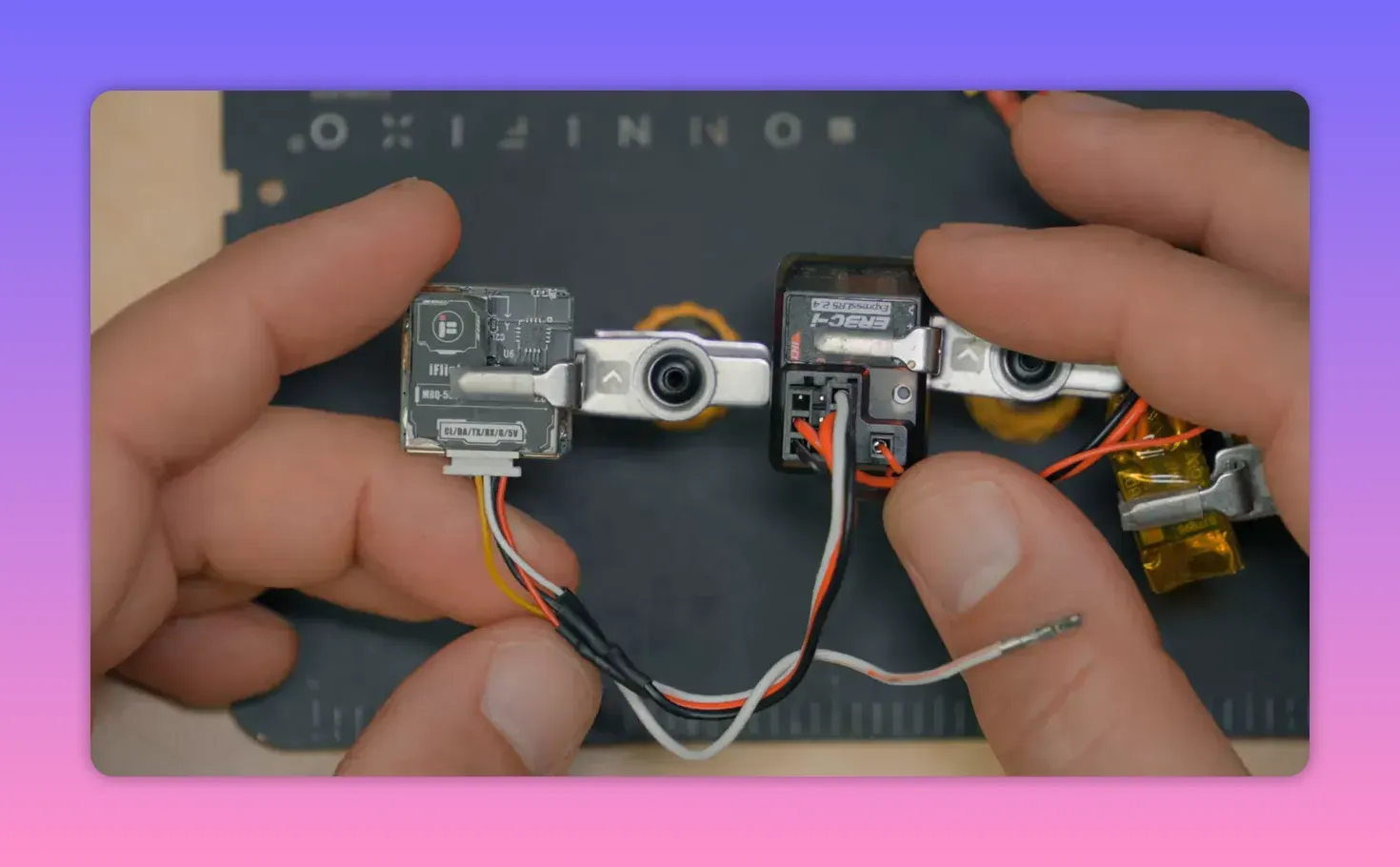
The wiring is refreshingly minimal. Power and ground go to the GPS as normal, but only the GPS TX line matters for data.
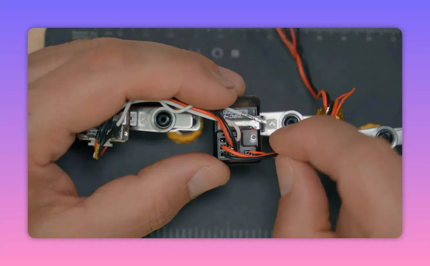
The GPS TX wire connects to the receiver pin configured as Serial RX. In Bardwell’s example, pin 3 became Serial RX, so the GPS transmit line went to the channel 3 signal pin.
The GPS RX pin stays disconnected. ELRS currently reads positioning data one-way only. The receiver listens; it does not talk back.
That missing return path matters because many flight controllers auto-configure GPS modules. They can change baud rate, update rate, and other settings. Here, there is no flight controller doing housework, so the GPS often needs manual configuration.
The bit that usually breaks: GPS protocol and baud rate
Out of the box, many GPS modules will not work. ExpressLRS currently supports NMEA, not UBX binary messaging, and it expects the GPS UART to run at 115200 baud.
Plenty of GPS units default to 9600 baud or some other speed. Many support both NMEA and u-blox modes, but the baud mismatch alone is enough to make the whole setup look dead.
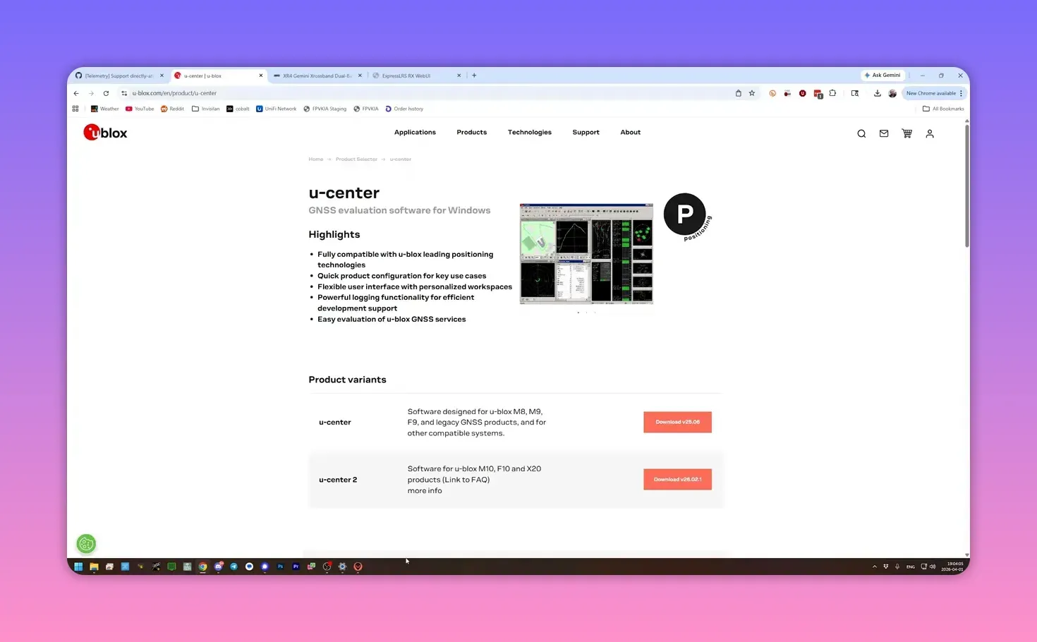
Set the GPS baud rate with u-center
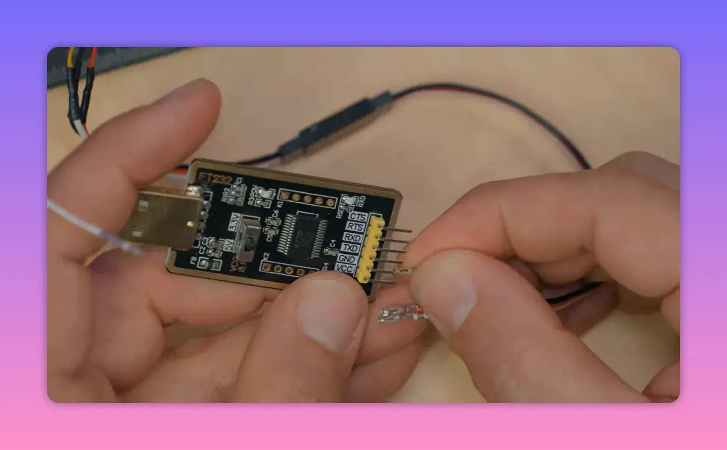
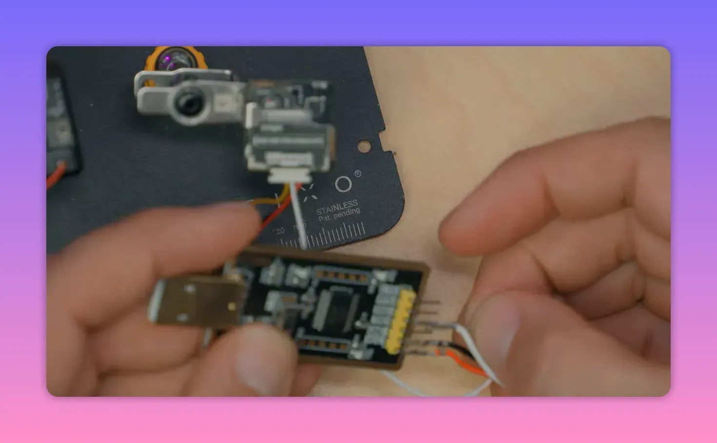
For this job, Bardwell used u-center, the u-blox configuration tool, plus an FTDI adapter to connect the GPS module to a computer. A handy adapter with labelled pins and switchable 5V or 3.3V output makes life less irritating.
A chopped servo extension also helps. It turns a GPS lead into something easy to push onto FTDI pins without inventing a new wiring crime.
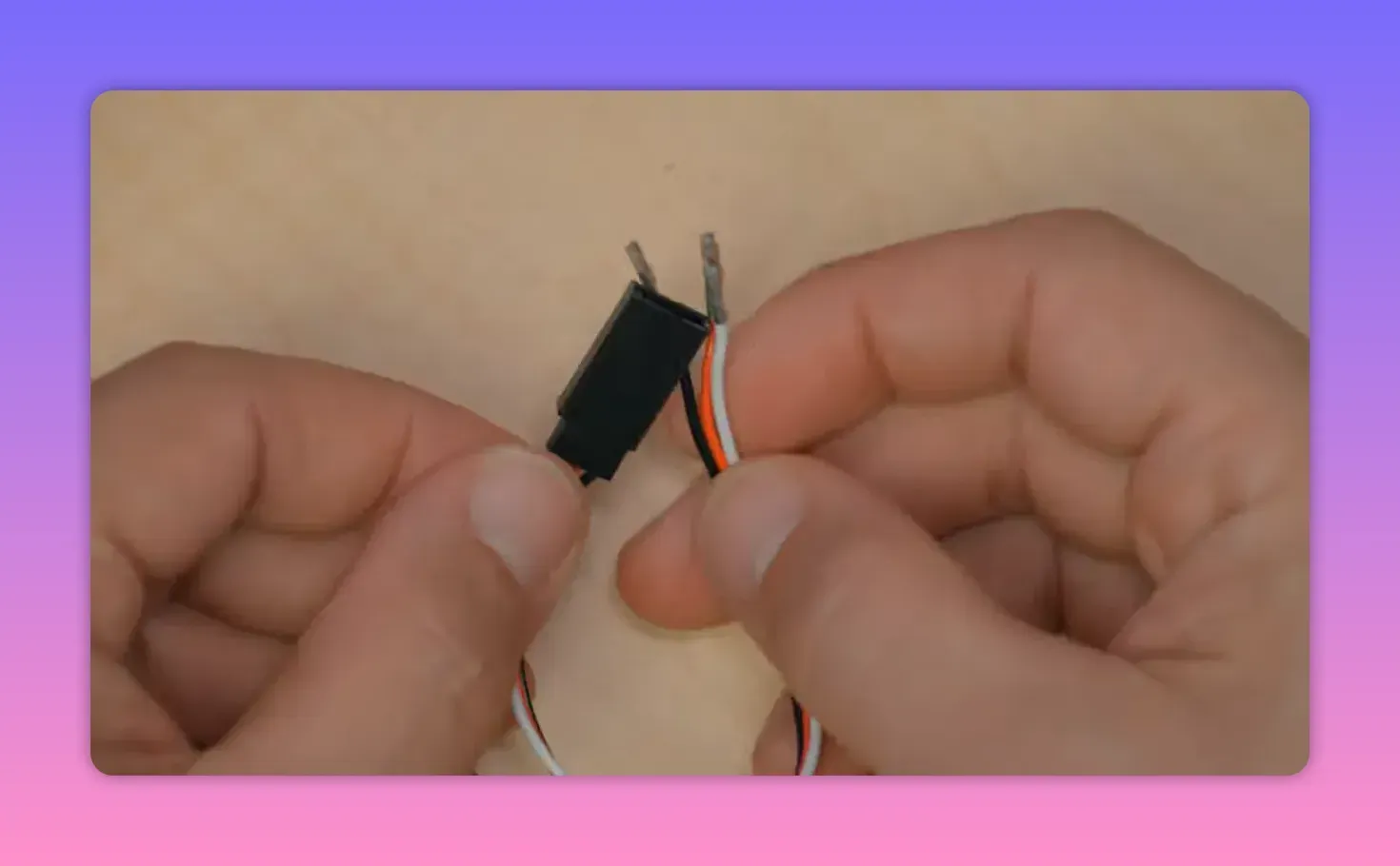
Unlike the ELRS setup, configuring the GPS requires bi-directional serial. So connect GPS TX to FTDI RX, GPS RX to FTDI TX, plus power and ground.
u-center 2 for M10 GPS modules
If the GPS is based on an M10 chip, use u-center 2. That version wants account logins and other administrative theatre, but M10 support lives there.
After plugging in the FTDI adapter, add a new data source using the detected COM port. Let the software auto-detect the baud rate if possible. That saves guessing, which is always nice.
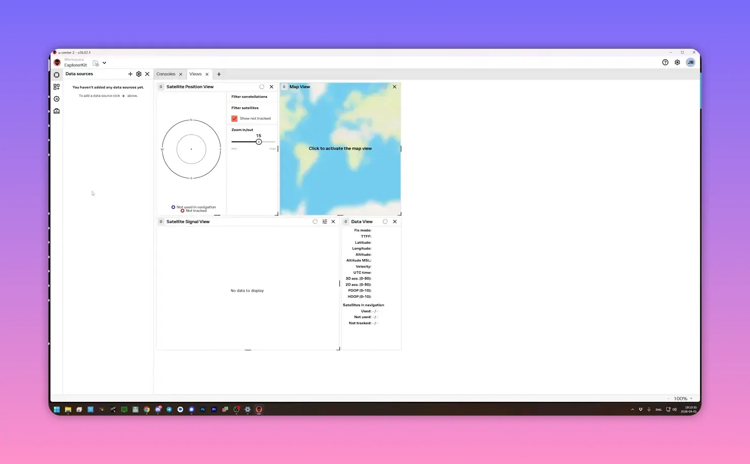
Once connected, the console should show incoming messages and satellite data. Indoor lock may fail, but serial communication should still be visible.
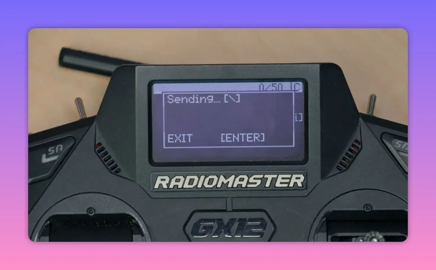
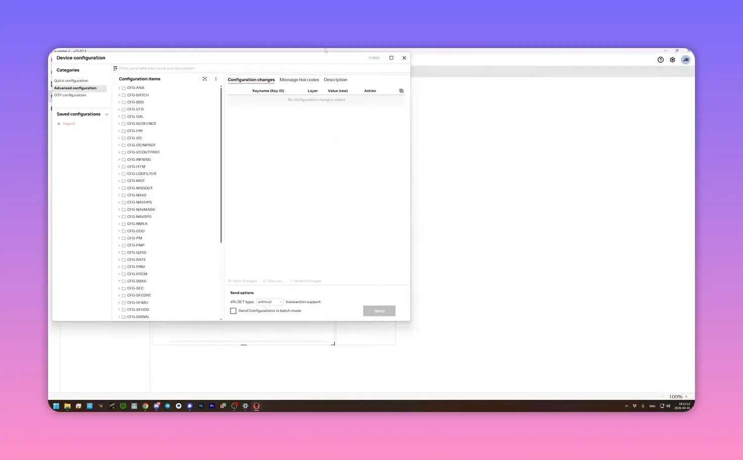
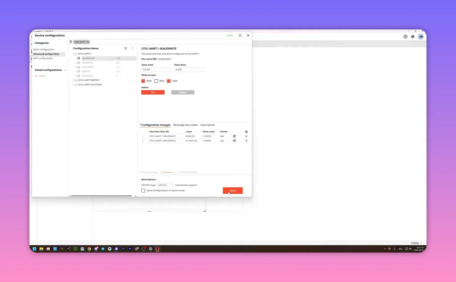
To change the baud rate, open Tools and Services, then Device Configuration, search for CFG-UART1, and set the baud to 115200. Write it to RAM and flash, then send the setting.
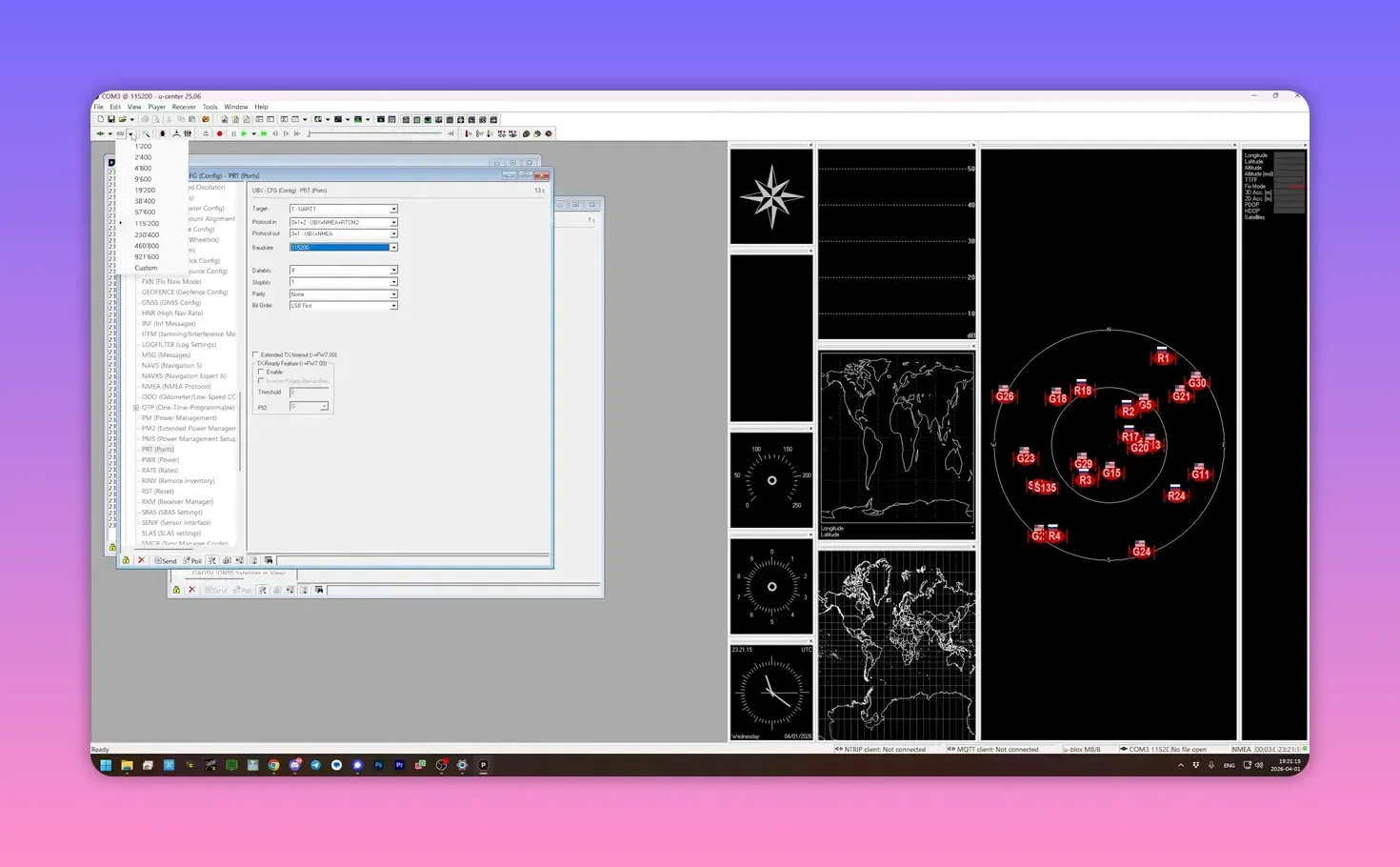
u-center classic for M8 or M9 GPS modules
For an M8 or M9, the older u-center app still works. Pick the COM port manually, then choose the current baud rate. There is no clever auto-detect here, so some trial and error may be required.
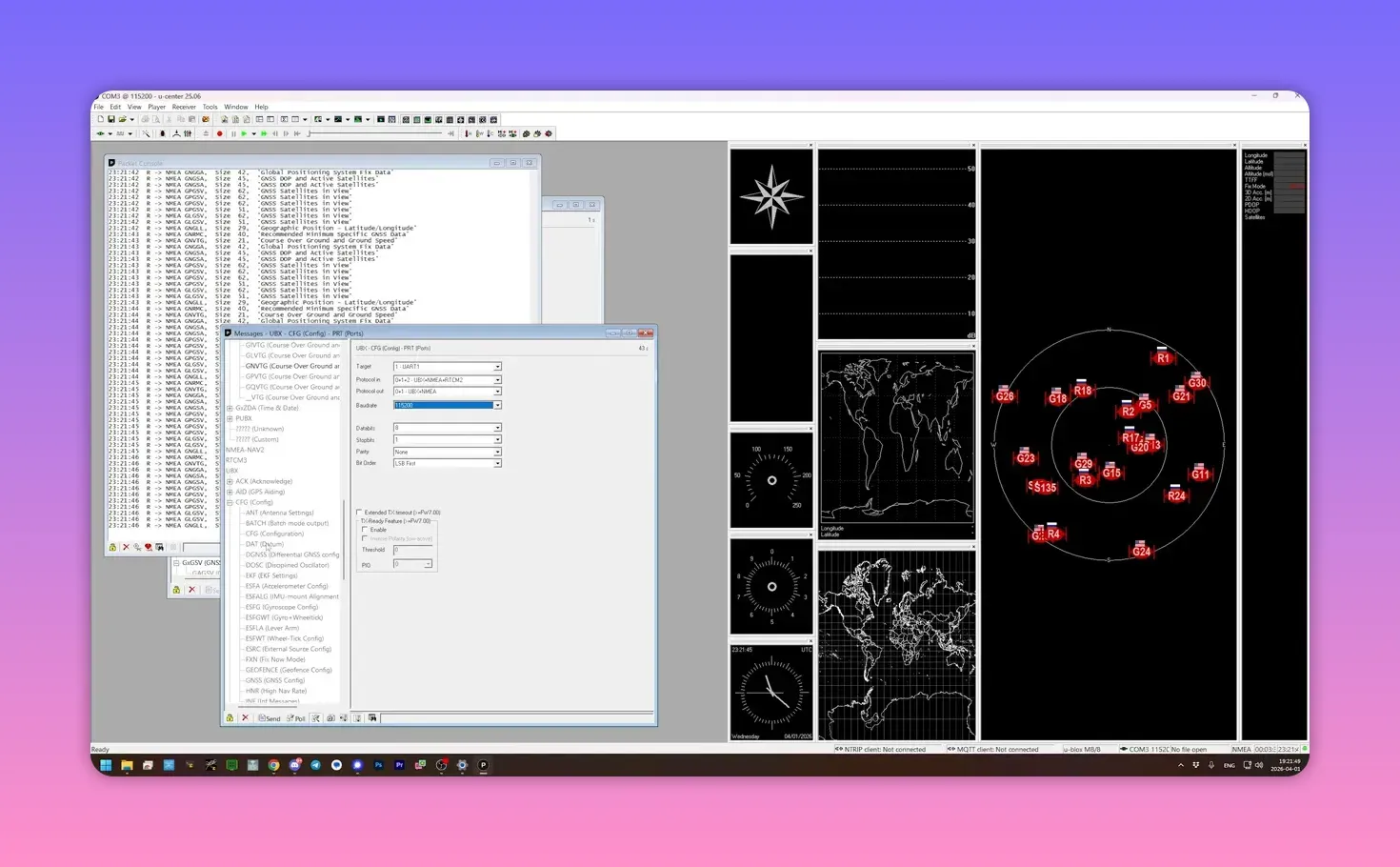
After connection, open the message view and navigate to UBX > CFG > PRT. Select UART1 and change the baud rate to 115200.
Press Send. The link will drop if the module was not already at 115200 baud, which is expected, not a software tantrum.
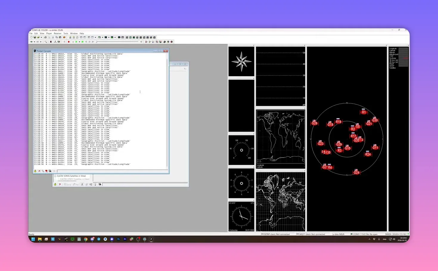
Then change the host-side baud rate in u-center to 115200 and reconnect. If the packet console starts scrolling again, both sides now agree.
That still does not make the setting permanent. To save it across power cycles, go to UBX > CFG > CFG, select Save Current Configuration, tick BBR and Flash, and send it.
Power-cycle the GPS and reconnect at 115200 to confirm the change stuck. If messages still stream after a fresh power-up, the GPS is now ready for ELRS.
Check that ELRS is actually receiving GPS data
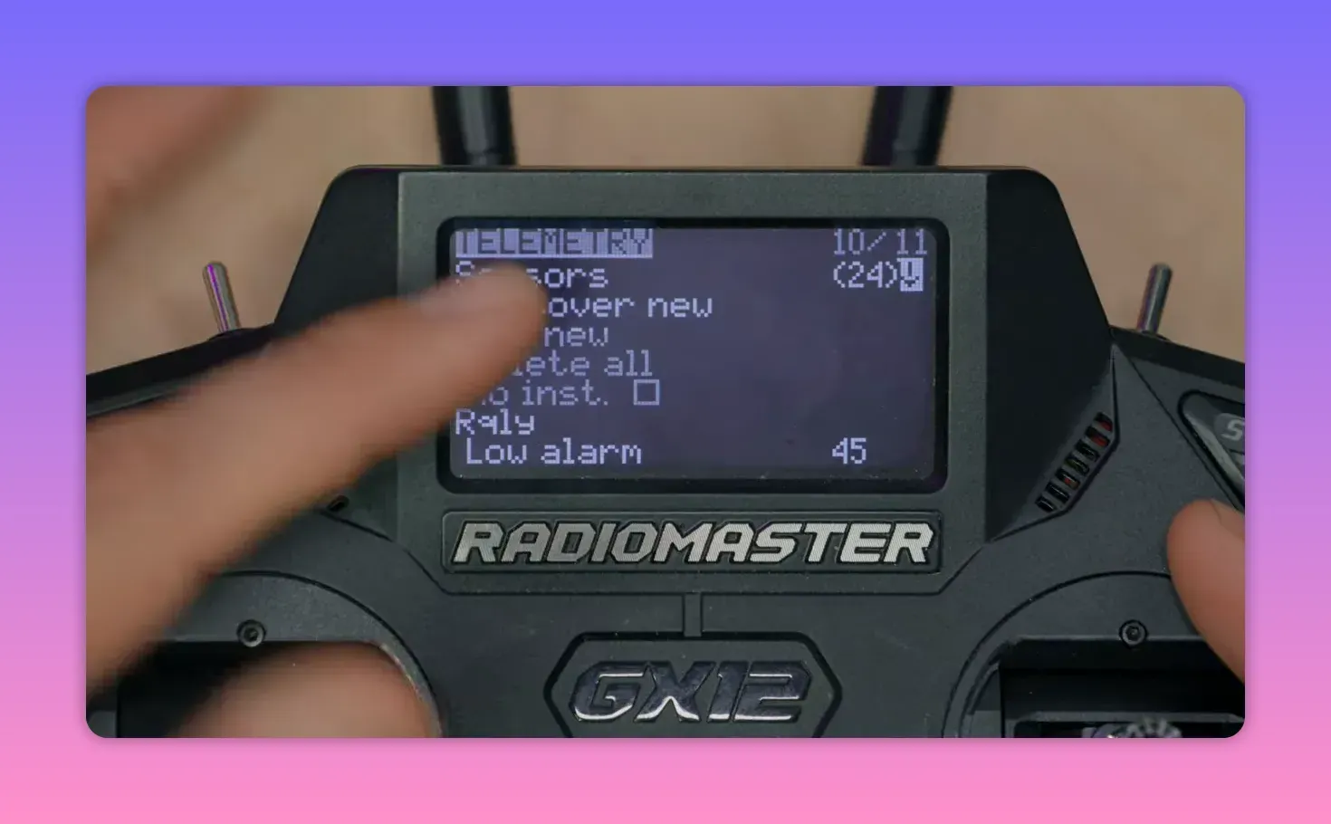
Reconnect the GPS to the receiver and open the radio’s Telemetry page in EdgeTX. If GPS sensors have never been discovered on that radio, run Discover new sensors.
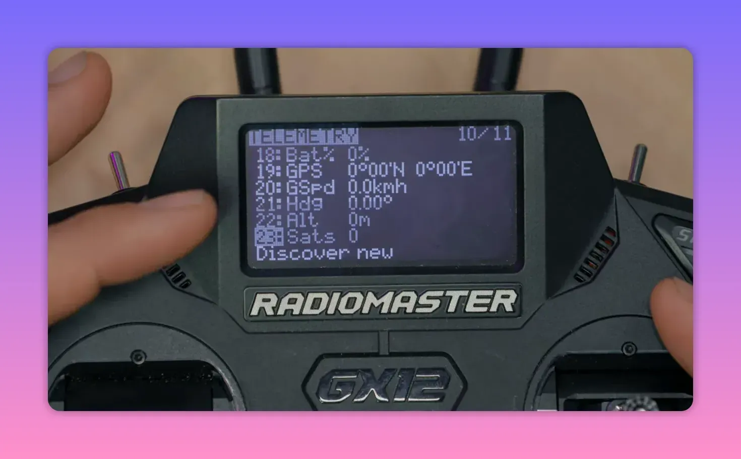
On the telemetry list, the GPS fields should appear and show update activity. Indoors, there may be no valid position yet, but active sensors mean the receiver is talking to the GPS.
Once the model goes outside and gets a lock, coordinates and satellite count start filling in. At that point the setup stops being theoretical and starts being useful.
What to do with the coordinates
Raw telemetry fields are not especially elegant. Still, they are the foundation for everything else, from a basic coordinate display to a proper map track.
Option 1: show GPS data on the radio
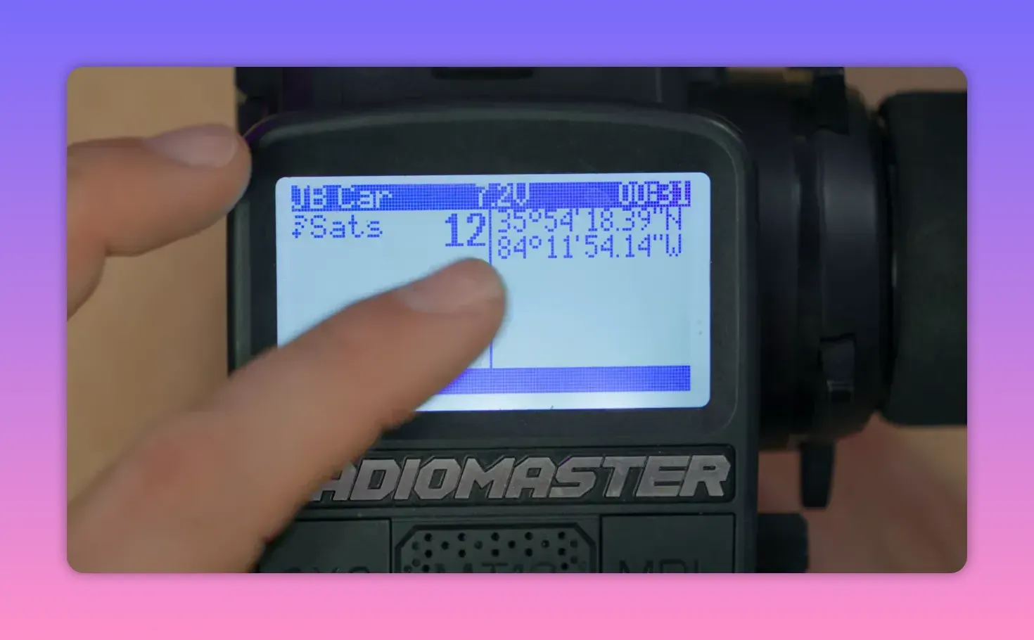
On a black-and-white EdgeTX radio, create a new display screen and set it to Nums. Assign one field to Sats and another to GPS.
That gives a dedicated telemetry page showing satellite count and the current coordinates with more detail than the compressed sensor list. It is simple, and simple does sometimes win.
On colour touchscreen radios, the same idea works through widgets instead of the older screen layout. A telemetry widget can sit right on the main screen if desired.
Option 2: turn GPS telemetry into a QR code
There is a more practical trick for recovery. A Lua script called GPS QR generates a QR code from the GPS telemetry so a phone can scan it and open the location directly in a map app.
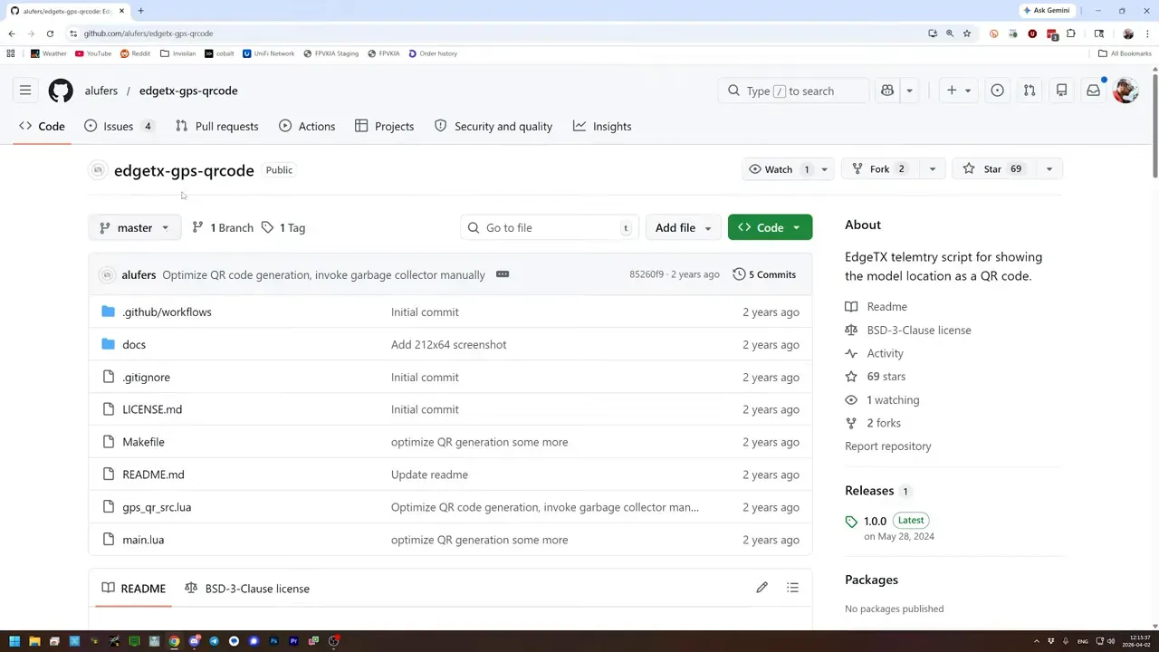
The script belongs in SCRIPTS/TELEMETRY, not in the usual TOOLS folder where many Lua scripts live. That catches people out because, naturally, software likes little surprises.
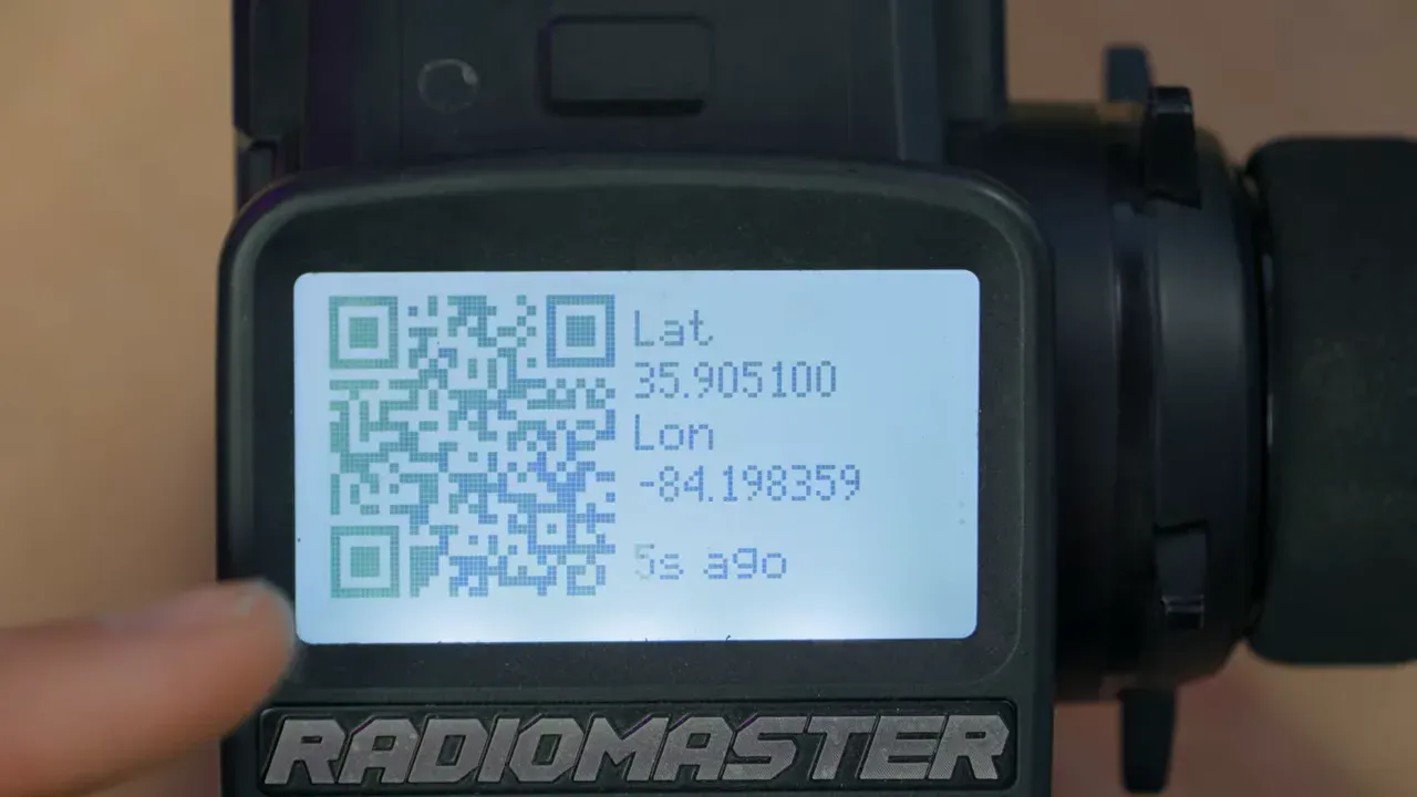
After copying the script to the radio over USB storage mode, create a telemetry screen of type Script and assign GPSQR to it. Bardwell also kept satellite count on another screen, which is sensible because a location without lock is just decorative text.
Now pressing the telemetry key can show a QR code generated from live latitude and longitude. Scan it with a phone, tap View on map, and the coordinates open directly in mapping software.
For finding a crashed model, that is far less annoying than reading out decimal coordinates and manually typing them into a handset while standing in a field muttering at electronics.
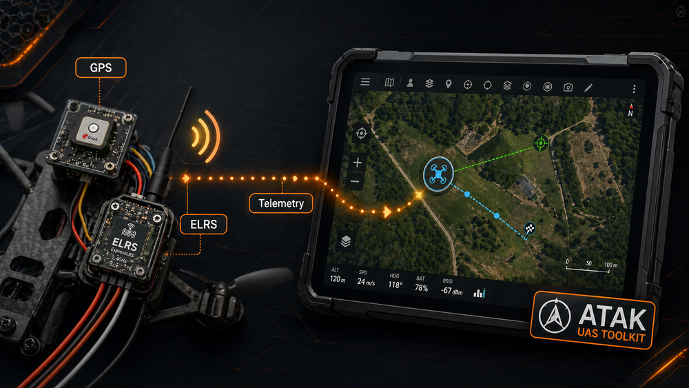
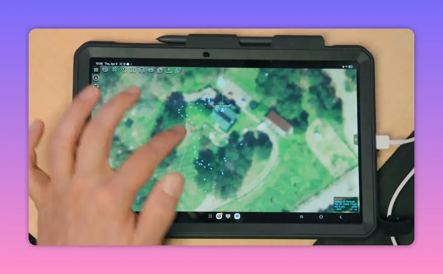
Option 3: live mapping with ATAK
If static coordinates are not enough, ELRS telemetry can feed a live map. One route is ATAK, paired with the UAS Tool plugin.
There is one gotcha straight away: download ATAK from tak.gov, not from the app store. The required version in this setup was 5.6, not the then-latest 5.7.
The UAS Tool plugin also comes from the ATAK ecosystem and requires an account to download. Installation is not hard, but it is picky enough that following a dedicated setup guide is a good idea.
Once installed, ATAK can show a map, personal position, team members, and tracked devices. The UAS Tool plugin adds support for aircraft and similar objects, which is the part needed here.
Feed ELRS telemetry from EdgeTX into ATAK
To get radio telemetry into ATAK, the EdgeTX radio must output telemetry over USB. On the radio, open the Hardware page and change USB VCP from CLI to Telemetry Mirror.
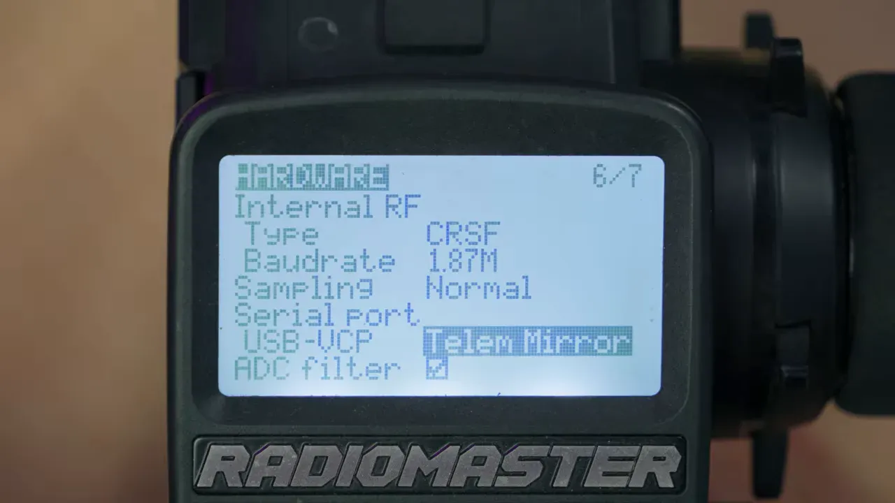
This mirrors Crossfire telemetry out of the USB port. It also means USB pass-through flashing for the ELRS module will stop working until that setting is changed back. Wi-Fi flashing still works.
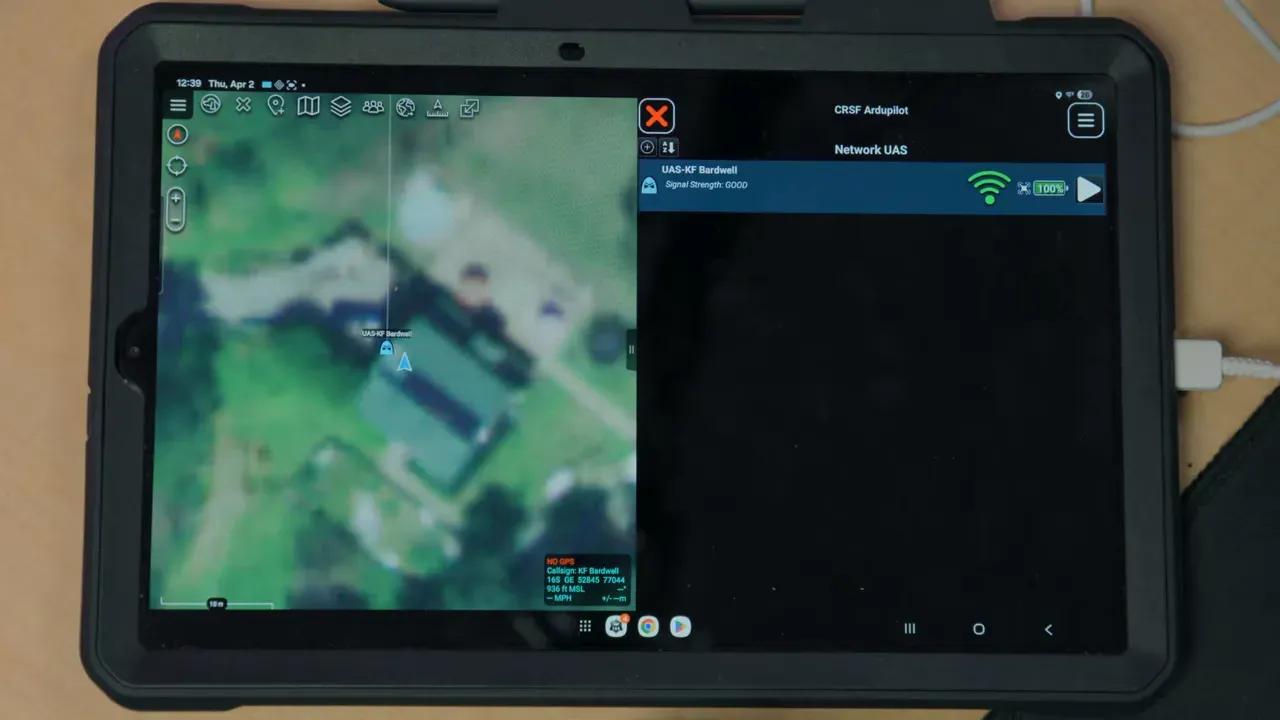
Connect the radio to the Android tablet by USB and select USB VCP on the radio. Then, inside UAS Tool, add a platform using Crossfire ArduPilot, set monitor mode to Serial, choose the radio as the serial device, and set the baud rate to 115200.
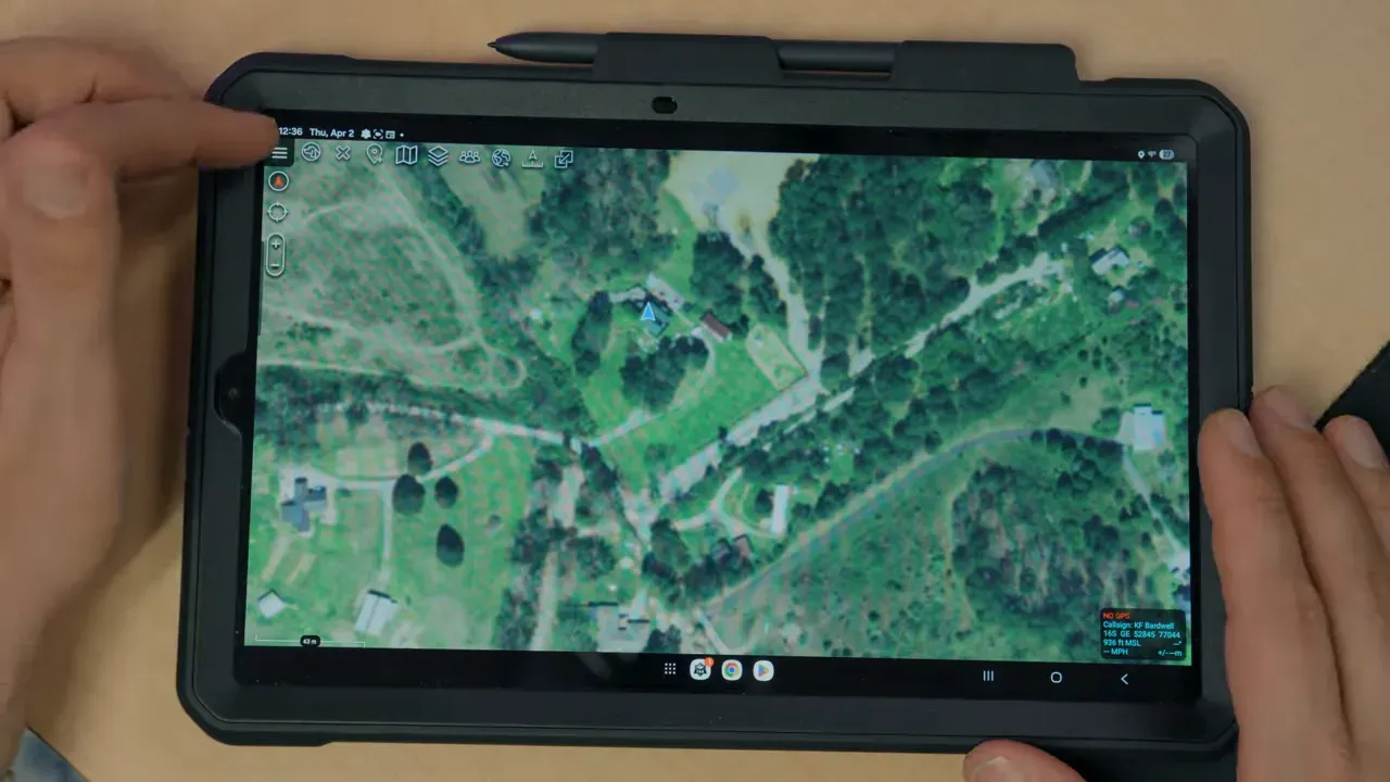
From there, ATAK can track the vehicle on the map. Turning on breadcrumbs records the path, and a follow option keeps the tracked object centred on screen.
Bardwell also notes that ATAK can display a video feed if the tablet has access to one, such as through an HDMI capture device. In more integrated systems, it can do a lot more than mere tracking.
Option 4: SquirrelCast, maybe
The other live-mapping option mentioned is SquirrelCast. It appears to target FPV use more directly and can show telemetry, a live flight path, and even DJI video on one screen.
Its big selling point is that it can use the ExpressLRS backpack over Wi-Fi, so there is no USB cable between radio and tablet. That is cleaner, less fiddly, and therefore suspiciously attractive.
There is, however, a snag. Bardwell could not get it working despite walking through the troubleshooting process and fixing several issues. So it exists, it looks promising, it costs a few dollars, and it may or may not behave.
Why this matters
This feature turns an ELRS receiver plus a GPS puck into a self-contained tracker for almost any RC vehicle. Cars, boats, and non-FC aircraft gain GPS telemetry without dragging in a full flight stack just to learn where they are.
That is useful for recovery, route logging, and live position tracking. It also shows how ELRS 4.0 keeps mutating from “radio link” into “Swiss Army serial bus with opinions”.
FAQ
Does this require a flight controller?
No. That is the whole point. The GPS connects directly to an ExpressLRS receiver, and the receiver sends GPS telemetry back to the radio.
Which ELRS version supports direct GPS on the receiver?
ExpressLRS 4.0 and newer. ELRS 3.x does not support this feature.
Can a PWM receiver be used for GPS tracking?
Yes. One PWM output is reassigned as serial TX/RX for the GPS. That costs one servo output, so channel count matters.
Does the GPS need both TX and RX connected to the receiver?
No. For ELRS receiver operation, only the GPS TX line is used, connected to the receiver’s serial RX pin. GPS RX is left disconnected.
What baud rate does the GPS need?
115200 baud. Bardwell also notes that ELRS currently supports NMEA data, not UBX binary messaging, so the GPS must be configured accordingly.
How can the GPS position be used once telemetry is working?
Several ways: display coordinates and satellite count on the radio, generate a QR code that opens the location in a map app, or feed telemetry into ATAK for live map tracking.
Can this work with ATAK?
Yes. EdgeTX can mirror telemetry over USB to an Android device running ATAK with the UAS Tool plugin. The radio’s USB VCP mode must be set to Telemetry Mirror.
Is SquirrelCast a good alternative?
It may be, but Bardwell did not get it working in this setup. It uses the ELRS backpack over Wi-Fi, which sounds excellent when it behaves.
Takeaway box
- ELRS 4.0 lets a receiver read GPS directly, so RC cars, boats, and servo planes can report position without a flight controller.
- PWM receivers work well, but one output becomes serial for GPS. No spare channel means no spare channel.
- The GPS usually needs manual setup: NMEA output and 115200 baud, typically done with u-center and an FTDI adapter.
- Once telemetry appears in EdgeTX, it can feed radio screens, QR-code map links, or live tracking in ATAK.
- SquirrelCast looks slick on paper, uses ELRS backpack Wi-Fi, and did not cooperate here. Such is software.
This article was based from the video GPS tracking for EVERY RC vehicle // ELRS TO ATAK!