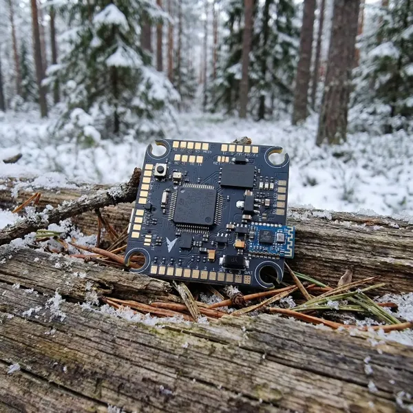
The Omnibus series of flight controllers from Airbot is one of the most popular options available for BetaFlight pilots. However, apart from a pinout diagram you get with the board, there is little other information available for the latest boards. In this guide, we hope to rectify that and help you to get the most from your flight controller.
What’s New in V6?
Apart form a new board layout that includes new soldering pads, instead of through hole connectors, the following things that have changed:
- New soldering point pads instead of through hole connectors. Larger pads for ground and power.
- New firmware target: OMNIBUSF4FW (in BetaFlight) / FIREWORKS V2 (in iNav) – for Betaflight, after flashing, go to CLI and type (without quotations): “set gyro_to_use = second” , and save to get the IMU working. The IMU roll offset needs to be set to 180 degrees.
- 5x UART Ports
- 5V 1A and 8V BEC for FPV camera
- Current source jumper selector
Looking for the Omnibus F4 V5 guide? Read it here.
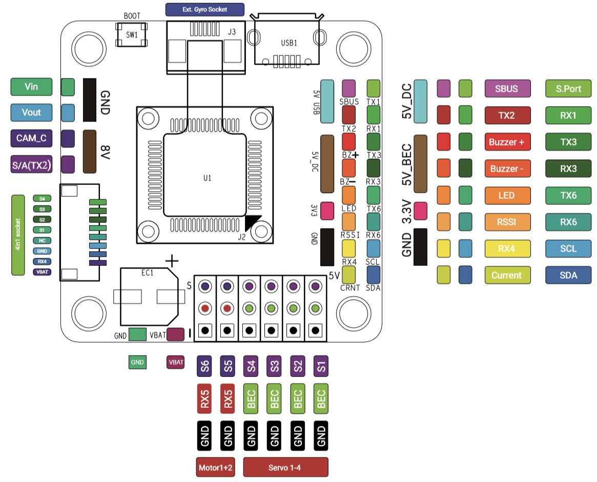
Omnibus F4 V6 Pinout
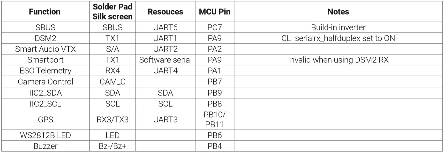
Resources
The table below shows what each pad is assigned to within betaflight if you want to change your own resource mapping (for advanced users only).
Flashing Firmware (BetaFlight)
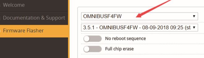
The Omnibus V6 uses the target OMNIBUSF4FW when flashing firmware.
Because this board as a slightly different IMU layout to the Fireworks you will notice that the gyro is not working after you flash the firmware. Do not worry as you just need to run some CLI commands after flashing the firmware to get the gyro to work. Just go to the CLI tab and enter the following commands:
set GYRO_TO_USE = SECOND
save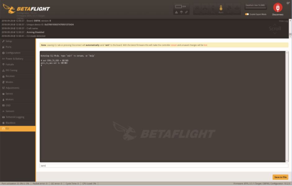
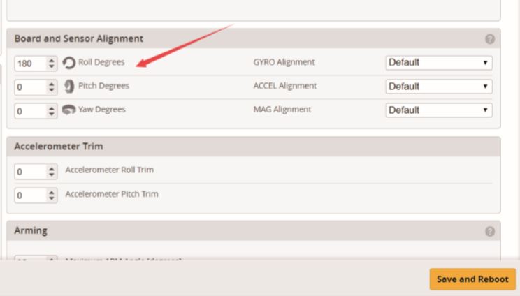
The last thing you need to do is set the roll angle on the sensor alignment section (Configuration Tab) to be 180 degrees. This is because the omnibus F4 V6 has the IMU mounted on the opposite side to the fireworks board.
Flashing Firmware (iNav)
Oddly, flashing firmware in iNav is significantly easier than it is in Betaflight.
In iNav, once you have your drivers installed correctly, boot the board into DFU (though you may find the firmware flash tool will reboot into DFU for you) and select the FIREWORKSV2 target.
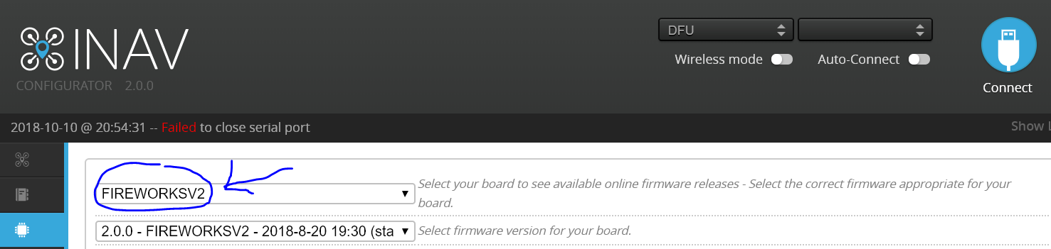
Once you’ve selected the correct target and your preferred firmware version, you can load and install the firmware as usual using the buttons in the bottom right of the configurator.
There are no additional steps required to flash iNav.
Powering your board
Just like with the previous omnibus F4 boards you have the option to power it via your flight battery or via a 4in1 ESC. You can also power it via a 5V BEC from a servo if you wanted (need to solder the 5V jumper, see solder jumpers section).
Powering via your flight battery
If powering directly via your battery voltage you simply need to solder the power to VBAT and the ground to the GND pad right next to it.
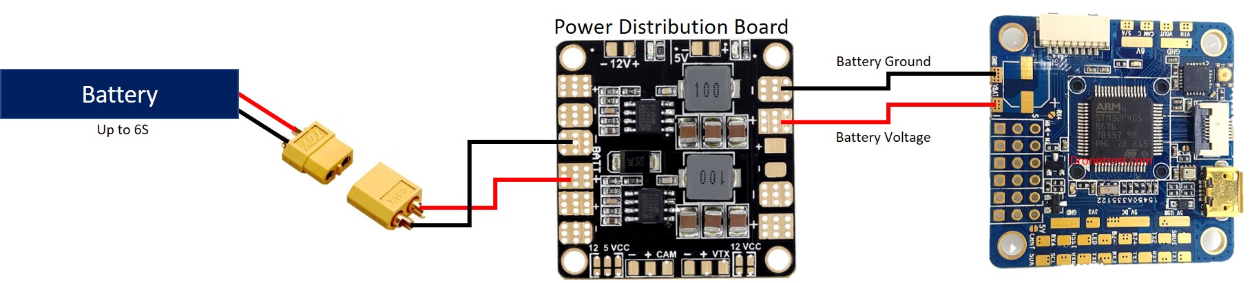
Do not accidentally confuse the VIn pad with voltage input. VIn is for video input.
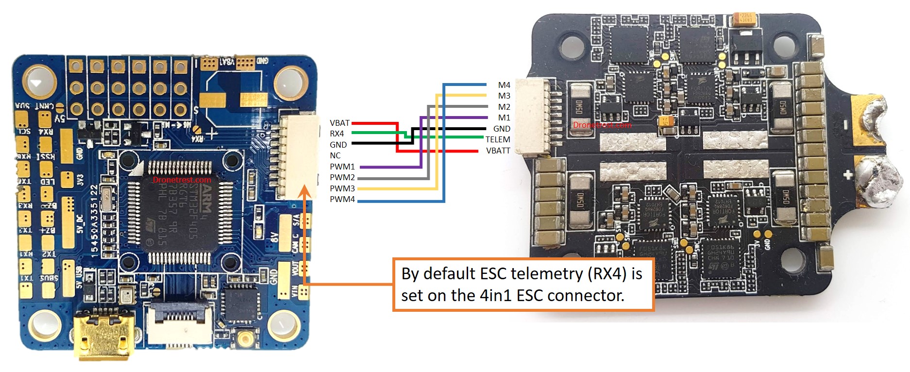
Powering via a 4in1 ESC (BLheli_S)
This board as a standardised 8 pin JST-SH socket for connecting directly with a 4in1 ESC. It plugs in directly to the Typhoon or Tekko ESC, but if using another ESC, just double check the wire order to make sure it is correct.
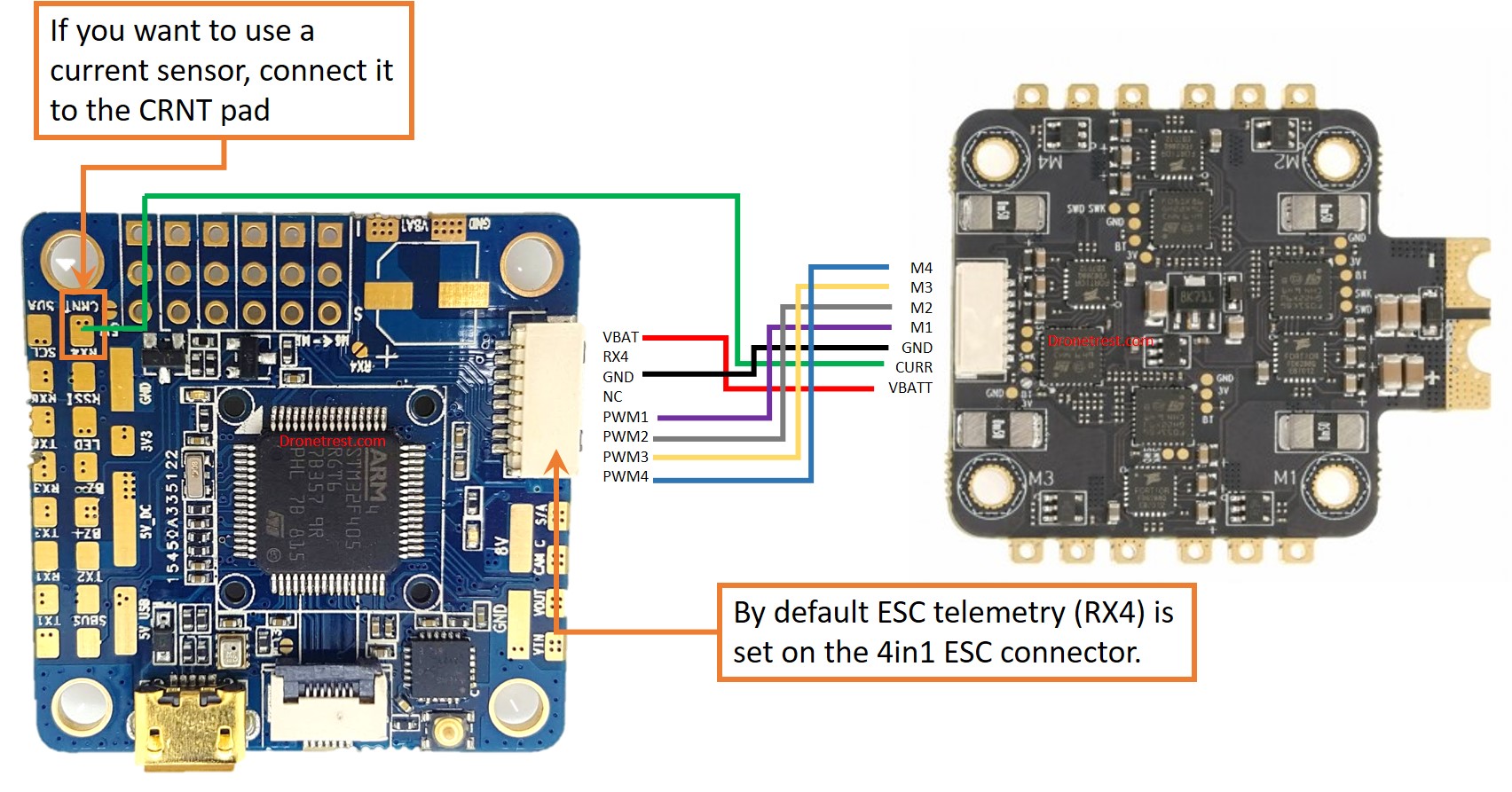
Powering via a 4in1 ESC (BLheli32)
Blheli32 ESC allow you to use ESC telemetry (optional) but since most include a telemetry wire it is convenient to connect it directly to the 8 pin JST-SH socket as shown in the diagram below.
Connecting your Receiver
Connecting your receiver to the omnibus is not much different from any other flight controller. The Omnibus V6 does not support PPM receivers so you have to use a serial based receiver. In this section I will show you how to connect some of the common types of receivers.
- SBUS pad has built in hardware inversion making it ideal for inverted SBUS receivers like the ones from Frsky.
- Non inverted serial receivers (Spektrum Satellite) are connected to the RX1 pad (diagonal across the SBUS pad).
- If using a 5V receiver, it is best to power it via the 5V_USB rail so that it will get power when you connect only USB.
- If using a Spektrum Satellite receiver you can power it via the 3V3 pad
Connecting an SBUS receiver
You connect your SBUS receivers (SBUS) to the SBUS pad. The SBUS pad has built in hardware inversion, making it ideal to connect your Frsky receivers.
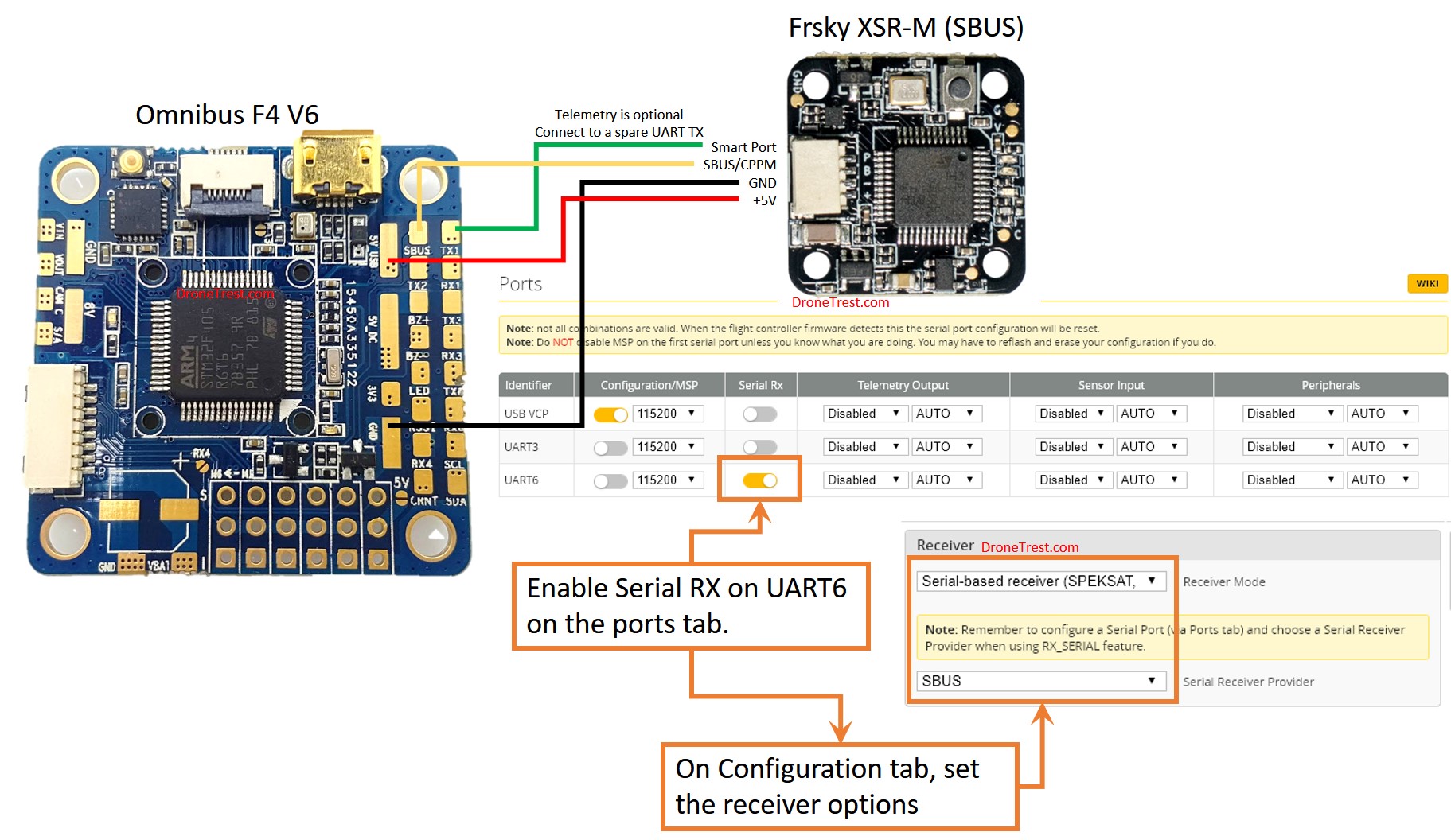
To enable the SBUS pad you first need to enable Serial RX on UART6 in the ports tab. Save and reboot FC. Then go to the configuration tab and select serial-based receiver and SBUS in the receiver options box.
Using Smart Port Telemetry
If your Frsky receiver supports smart port telemetry, you just need to connect it to the TX1 pad as shown in the diagram above (green wire).
However, the problem on the omnibus is that the UART1 ports do not have a serial inverter built in (required for smart port telemetry). To overcome this you simply need to use soft serial which emulates the inverter via software. Fortunately, we have a quick guide that walks you through the process of using soft serial:
Connecting your FPV Gear
The omnibus uses a built in OSD, so you need to route the video signal from your camera through the FC before it is sent to your VTX. The omnibus V6 now uses a separate 8V circuit to power your FPV gear, this pad is conveniently located right next to the FPV connectors. This pad can be used to power both your VTX and FPV camera. An example of how to connect your FPV gear is shown in the diagram below.
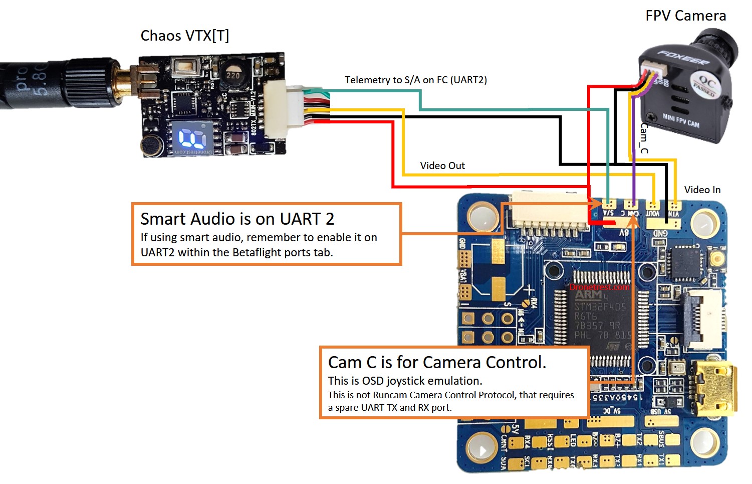
Something to take care of here is that if you want to use smart audio to control your VTX via the OSD menu is to enable smart audio on UART 2 in the ports tab.
Similarly if you camera supports OSD control (via a single wire), you can connect that directly to the CAM C pad to emulate the OSD joystick via the OSD menu on your omnibus. If you are using a Runcam that supports Runcam camera control protocol, then you do not use this pad, but rather a spare UART port (both TX and RX). For more information check out the Betaflight wiki, as it does not work with every camera out of the box.
Connecting a GPS and Compass
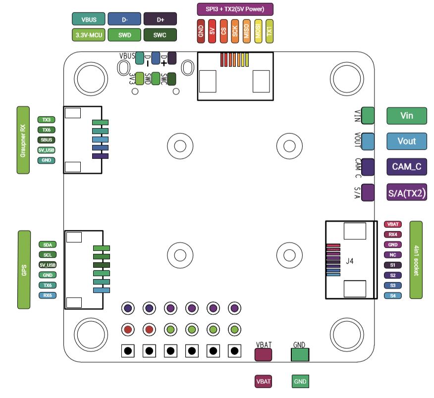
The omnibus F4 V6 includes a handy 6 pin JST-SH 1.0 connector that is compatible with most GPS/Compass modules. The GPS connector is on the bottom of the flight controller. It has both a UART 6 pin (for the GPS) and a I2C connector (for the compass).
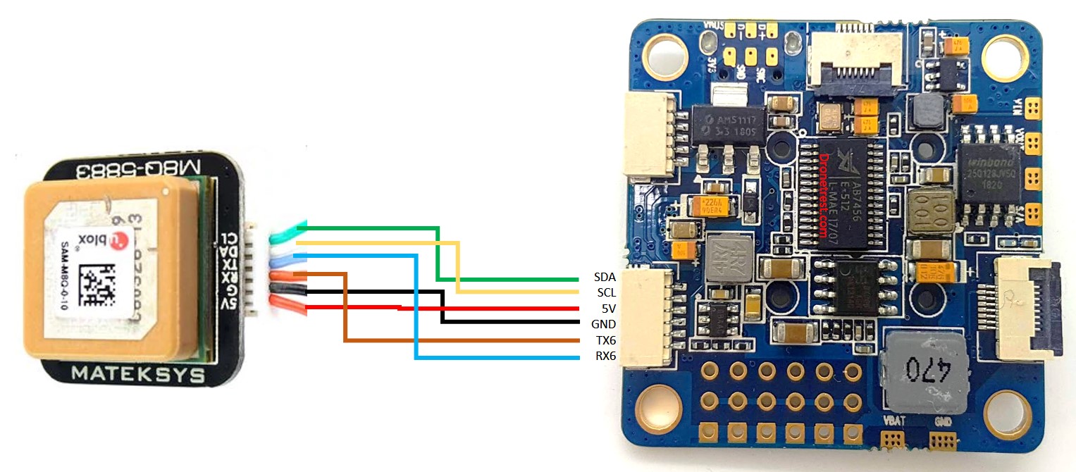
Once connected you simply need to enable GPS on the Ports tab within Betaflight/iNav. You may also need to enable the magnetometer, but once enabled the flight controller software should automatically pick up the compass. My advice here is that if using a compass, make sure you mount the GPS/Compass module as far away from any other electronics as possible to avoid magnetic interference, and also make sure it has a clear view of the sky.
Solder Jumpers
The Omnibus F4 V6 has three solder jumpers, for most setups you can simply ignore them. But depending on some specific setups you may want to take advantage of them.
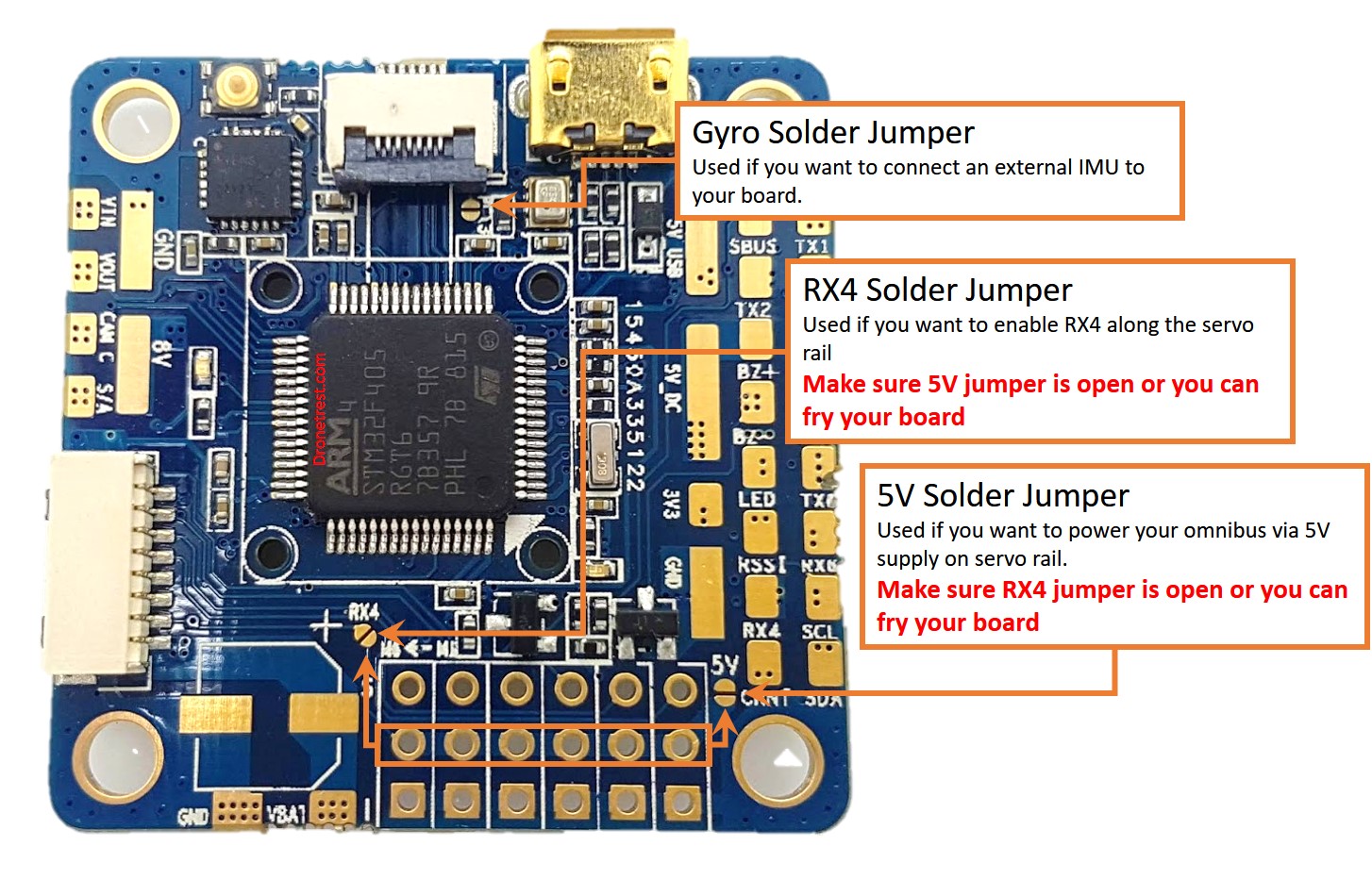
Gyro Solder Jumper
When this jumper is closed it will enable you to use an external Gyro connected to the Gyro socket. As an example this lets you use a vibration damped gyro box like the ones used on the Omnibus Fireworks. If you want to use an external gyro you just need to use the set GYRO_TO_USE = FIRST command via the CLI.
RX4 Solder Jumper
If you are using individual BLheli_32 ESC connected to the servo rail, you may want to use ESC telemetry. By soldering this jumper closed, it will set the middle row of pins to UART4 RX. This lets you easily connect the ESC telemetry wires to the middle row to take advantage of ESC telemetry.
WARNING: Make sure that the 5V solder jumper is open, if not and you power your board you can damage the FC and also your ESC!
5V Solder Jumper
If you are using individual ESC, or Servos on a fixed wing aircraft, it is usefull to have 5V supply along the servo rail. With the 5V jumper closed, it will connect the middle row to the flight controllers 5V power rail. This lets you either power the omnibus via a 5V Bec, or you can also power your servos.
WARNING: Make sure that the RX4 solder jumper is open, if not and you power your board you can damage the FC and also your ESC!
Any questions?
I have not covered everything in this guide, so if something is not clear, or you want me to explain anything specific just ask and I can get that added as soon as I get some time.
Thanks for reading, if this guide helped you please share it with your friends or consider buying something from the links on our blog as we get a small commission to help fund this site!