In Chris Rosser's latest video, he unveils an extensive Ardupilot tuning guide that covers everything you need to know to get your drone flying perfectly. From hardware setup to initial calibration, this guide provides invaluable insights for both hobbyists and professionals alike.
Intro
Welcome to the ultimate guide for mastering your Ardupilot drone! In this post, we’ll explore the intricate details of setting up and tuning your drone using Ardupilot, a powerful flight control software. Whether you're a hobbyist or looking to venture into professional territory, this guide is tailored to ensure you get the most out of your drone. Let's jump right into the essentials!
What's in this guide?
This guide will cover the entire process of configuring and tuning your Ardupilot drone. We’ll discuss everything from hardware setup and wiring to software flashing and bootloader mode. Here’s a quick overview of what you can expect:
- Ardupilot tuning course for Pros
- Hardware on test drone
- Wiring components to the Ardupilot FC
- Flashing Ardupilot firmware
- Entering bootloader mode
Ardupilot tuning course for Pros
If you’re a professional looking to tune larger drones or require advanced features, consider enrolling in a specialized Ardupilot tuning course. This course offers tailored support, ensuring that your drone is configured for optimal performance, even if you're new to Ardupilot. With one-on-one assistance, you can achieve a precise and safe tuning setup.
Hardware on test drone
For this guide, we will be using a carefully selected set of hardware components that are well-suited for Ardupilot drones:
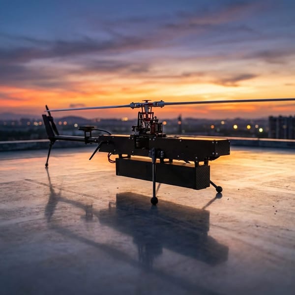
- AOS UL eight frame: A lightweight and versatile frame ideal for both acrobatic flying and autonomous navigation.
- Maytag H7A3 flight controller: This controller is compatible with Ardupilot and offers robust performance.
- iFlight BLITZ E55 ESC: A standard ESC that pairs efficiently with the flight controller.
- M10 GPS and compass module: Essential for accurate positioning, ensuring that your drone can navigate effectively.
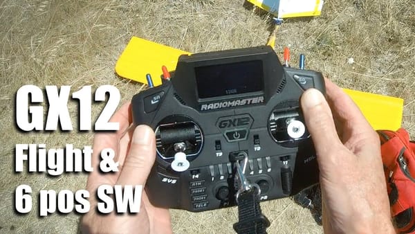
- ExpressLRS 2.4GHz receiver: Provides reliable communication between your drone and remote control.
- DJI O3A unit: For high-quality video transmission, though alternatives like DJI O4 or WalkSnail can also be used.
Wiring 4in1 ESC to Ardupilot FC
Wiring your ESC to the flight controller is a critical step. Ensure that the pinouts match; mismatched connections can lead to reverse polarity and potentially damage your flight controller. Follow these steps for a successful connection:
- Identify the power and ground pins on both the ESC and flight controller.
- Use tweezers to gently lift the plastic tab on the JST connector if pinouts do not match.
- Swap the wires as necessary, ensuring the correct orientation before pressing the tabs back down.
Repinning JST-1.0 connector
If you find that the power and ground pins are reversed, follow this simple guide to repin the JST-1.0 connector:
- Use sharp tweezers to lift the plastic tab carefully.
- Remove the wire from the connector and swap it with the adjacent pin.
- Reconnect the wires in the correct order and secure the tabs.

Wiring GPS and Compass module
Wiring the GPS and compass module is straightforward. Here’s how to do it:
- Connect SCL on the GPS to SCL on the flight controller.
- Connect SDA to SDA, TX on the GPS to RX on the flight controller, and RX on the GPS to TX on the flight controller.
- Don't forget to connect the ground and 5V wires, ideally to those powered by USB for easy setup.
Wiring Receiver
Wiring the receiver is even simpler. Follow these steps:
- Choose a different serial port on the flight controller.
- Connect TX on the receiver to RX on the flight controller and vice versa.
- Connect ground and 5V from the receiver to the flight controller.
Wiring DJI Air Unit
Wiring the DJI Air Unit involves similar steps:
- Select another serial port for connection.
- Wire TX on the Air Unit to RX on the flight controller and RX on the Air Unit to TX on the flight controller.
- For power, use an onboard BEC or connect directly to battery voltage if supported.
Flashing Ardupilot
If your flight controller comes pre-flashed with another firmware, you’ll need to flash Ardupilot yourself. Here’s how:
- Visit firmware.ardupilot.org and navigate to the Copter section.
- Download the latest firmware for your specific flight controller target, ensuring you select the version with a bootloader.
- Install STM32 Cube Programmer software to facilitate the flashing process.
Downloading correct firmware
Ensure you download the correct firmware by following these steps:
- Navigate to the 'latest' folder on the firmware download site.
- Locate your specific flight controller model.
- Download the Arducopter with bootloader hex file to guarantee future updates are seamless.
STM32 Cube Programmer
Once you have your firmware, install the STM32 Cube Programmer. This software is essential for flashing your flight controller with the Ardupilot firmware. Follow the installation instructions carefully to ensure that everything is set up correctly.
Entering bootloader mode
To flash your flight controller, you need to enter bootloader mode. Here’s how to do it:
- Locate the boot button on your flight controller.
- Press and hold the boot button while connecting the USB cable.
- This will allow your flight controller to enter bootloader mode, ready for flashing.

Connecting to STM32 Cube
To establish a connection with the STM32 Cube, locate the USB port labeled USB1 on your flight controller. This port should display the serial number of the STM32 microcontroller. If everything is functioning correctly, click on the connect button, and you should see a stream of data representing the current state of the chip.
Full Chip Erase
Before flashing the Ardupilot firmware, it's essential to perform a full chip erase. Navigate to the erasing and programming menu within the STM32 Cube software. Click on the full chip erase button and confirm the action. This process will wipe all existing data on the flight controller, preparing it for the new firmware.
Flash Ardupilot FW
With the chip erased, the next step is to flash the Ardupilot firmware. Select the new firmware path where you previously downloaded the Arducopter with bootloader. Ensure that you check the options for verifying programming and running after programming. You can also tick the full chip erase option, but since you've already done it, it's optional. Once ready, hit the start programming button to initiate the flashing process.
Connect to Mission Planner
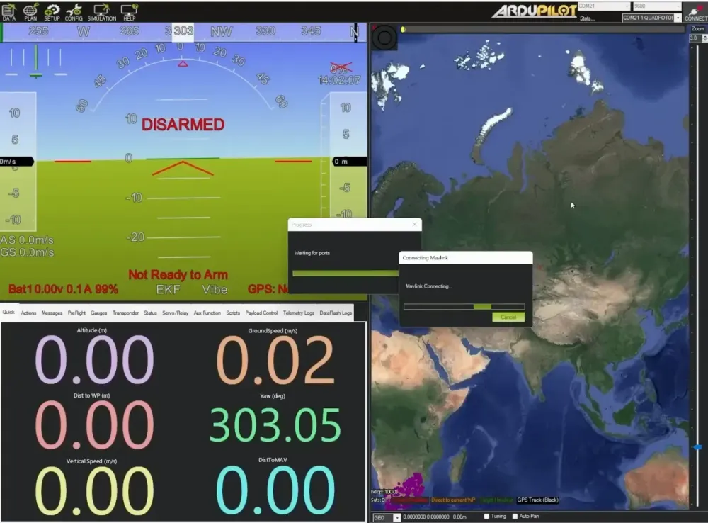
After flashing the firmware, power cycle the flight controller by unplugging and replugging the USB connection. Now, open Mission Planner and set the communication port to auto. Click connect, and if everything is set up correctly, you should see the MAVLink connection established, followed by a loading of parameters. This confirms that the firmware flash was successful.
Log Download Bug and Fix
It's important to note a known issue with the latest version of Mission Planner, version 1.3.82, which makes downloading logs over USB extremely slow and almost unusable. To avoid this, you can either revert to version 1.3.81 or check for beta updates via the help menu in Mission Planner. Applying the beta updates will help resolve this logging bug, allowing for smoother log downloads.
Setup Frame Type
Now that your flight controller is connected, navigate to the setup tab in Mission Planner. Under the mandatory hardware section, you will find the option to select the frame type. Ardupilot supports various frame classes based on the number of motors. For example, you can choose from quadcopters, hexacopters, and more. In this case, we will select the quadcopter class and, specifically, the V-type configuration for our UL eight frame.
Setup Initial Tune Parameters
Next, you’ll set the initial tune parameters. This includes entering the prop size in inches and the battery cell count. If you're using a 6S pack like I am, enter '6' for the cell count. You can manually input the fully charged and discharged cell voltages or select the battery chemistry from a dropdown menu to auto-populate these values. It's also advisable to check the box for suggested settings for firmware version 4.0 and above, which includes settings for battery fail-safes and altitude limits. After setting everything up, click on calculate initial parameters, then write those parameters to the Ardupilot firmware.
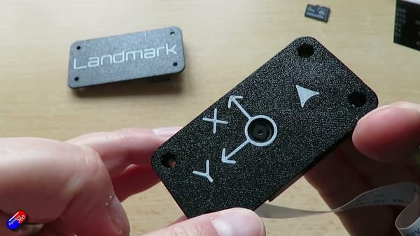
Setup Board Alignment
After configuring the initial parameters, it’s time to set up the board alignment. You only need to make adjustments if your board is oriented differently from the manufacturer’s default. To change the orientation, go to the config tab in Mission Planner, access the full parameter list, and search for ahr_orientation. Set this parameter according to your board's orientation. For example, if you need to flip the board 180 degrees, set it to '8'. If using the standard orientation, leave it at '0'.
Accelerometer Calibration
With the board orientation set, proceed to calibrate the accelerometer. Under the setup tab, find the mandatory hardware section and click on accelerometer calibration. Follow the on-screen instructions: hold the drone level and click done, then place it on its left side, then right side, nose down, nose up, and finally on its back, clicking done after each position. This calibration ensures that the drone maintains stability during flight.
Compass Calibration
Once the accelerometer calibration is complete, move on to calibrating the compass. In the onboard mag calibration section, click start. Similar to the accelerometer calibration, hold the drone level and perform a slow 360-degree rotation to the left and right. Repeat the process on the left edge, right edge, nose down, nose up, and finally on its back. If calibration fails, ensure the compass is not near any electrical interference or magnetic fields, and repeat the calibration process.
Once the compass is calibrated, it's time to check your radio channels. Ensure your receiver is bound to your transmitter. For ExpressLRS, quickly power the receiver on and off three times to enter binding mode, indicated by a double flash of the LED. Use the bind command in the ExpressLRS Lua script on your radio to complete the binding process. After binding, verify that all channels are populated with green bars in Mission Planner.
Radio Calibration
It's vital to check that the center stick positions are set to exactly 1500. Adjust the trims on your radio to achieve this. The low stick position should read less than 1000, while the high stick position should exceed 2000. If everything is aligned, you’re on the right path to a successful flight experience with your Ardupilot drone.
Finally, complete the radio calibration process. This involves ensuring all channels are responding correctly and that the sticks return to their neutral positions. The calibration process is crucial for achieving the best performance from your drone. If you encounter any issues, revisit the binding process or check your wiring connections. With everything configured correctly, you’re now ready to take to the skies!
Servo Calibration
First up, let's dive into servo calibration. For a straightforward Arducopter setup, your servo outputs will correspond to the motor outputs for your ESC. Set your servo outputs one to four as motor one to four. Keep in mind that if you're using a typical four-in-one ESC that doesn’t conform to the Ardupilot motor layout, the servo and motor numbers may not align. Don't worry; we’ll sort that out during the motor test later.
Serial Port Assignments
Next, we need to configure the serial ports. This setup relies on how you've wired your flight controller, so refer back to your notes to recall which devices are connected to which serial ports. For instance, serial port one (UART one) is typically set to the MAVLink 2 protocol. Leave that as is; it's crucial for USB connectivity. If you connected your receiver to serial port two, set the protocol to RC in, which will auto-detect the baud rate. For UART three, connect your GPS and set it to GPS protocol with a baud rate of 57600. Lastly, for the air unit on UART six, set the protocol to DisplayPort with a speed of 115200.
ESC Calibration
Now, let’s move on to ESC settings. Head to the ESC calibration tab, but be cautious—do not click the calibrate ESCs button if you’re using a digital ESC. This can cause the flight controller to get stuck in a calibration loop. Instead, set your ESC type to DShot 300, as using DShot 600 is unnecessary with Ardupilot. Set your output PWM minimum to 1000 and maximum to 2000, with the spin when armed typically around 5-10%. Finally, adjust the minimum spin to 10% for the lowest throttle setting during flight and set the maximum spin to 1.
Flight Modes
Next, we’ll configure the flight modes. You can find this setup in the flight modes tab. If you wish to control the flight modes with a different channel on your radio, go into the config tab, full parameter list, and search for flt_mode_ch. Change this to your desired channel—by default, it’s usually channel five (aux one). I have mine set to a three-position switch: top for stabilize, middle for altitude hold, and bottom for loiter. Adjust these settings as per your requirements.
Failsafe
Setting up your failsafe is a critical step in ensuring safety during flight. I recommend configuring it to return-to-home (RTL) and land. This way, if your drone loses connection or the battery voltage drops too low, it will automatically return to its launch point and land safely. Check that the low battery voltage is set correctly—21.6 volts is standard for a LiPo battery. Additionally, verify the load timer, which determines how long the voltage must remain below this threshold before the failsafe activates.
Battery Monitoring
In terms of battery monitoring, ensure you set the battery capacity correctly. If you want to track battery capacity in milliamp hours, make sure your current sensor is calibrated accurately. This will allow for a more nuanced failsafe based on remaining milliamp hours rather than just voltage. If you set the battery capacity to zero, it disables this feature, and the failsafe will revert to using just battery voltage.
Motor Order and Direction
Now we’ll conduct a motor test, but remember to remove the props first for safety. If you've set the server output one to motor one and so forth, your motor order might still be incorrect. It’s essential to test each motor to ensure it spins in the correct direction according to your wiring diagram. Write down which motor corresponds to which servo output to avoid confusion later. If your motors are not turning in the correct direction, simply tick the reverse checkbox for that servo output to correct it.
Check Compass Interference
With the motors sorted out, let’s check for compass interference. While this step isn’t mandatory, it’s a good precaution. For this test, put your props back on but flip them over so the drone is secured to the ground. Gradually ramp the throttle to 50-75% for about 5-10 seconds and monitor the compass readings. If interference is below 30%, you’re in the clear. If it’s between 30-60%, consider relocating the compass. Readings over 60% indicate you should definitely move the compass to a location further from any magnetic interference.
Gyro Settings
Now that we have all hardware configured, let's check the gyro settings. If your flight controller is an F7 or H7 board, ensure the INZ fast sample setting is enabled, and the INZ gyro rate is set to one (which corresponds to a 2 kHz rate). You can find these settings in the Mission Planner config tab under the full parameter list. These configurations are vital to avoid aliasing of motor frequencies, especially for smaller quads where frequencies can exceed 500 Hz.
Logging Settings for Tuning
Next, let’s configure the logging settings. Proper logging is crucial for effective tuning later on. Navigate to the setup tab in Mission Planner, then to optional hardware, and finally to FFT setup. Set the sample count per batch based on your INZ gyro rate. If set to 1 kHz, leave it at 1024. If it’s 2 kHz, increase the sample count to 2048 for better frequency resolution. Ideally, log only one of the IMUs to prevent overloads. Configure the logging bitmask to enable everything except mission commands, optical flow, camera, and raw IMU.
Hover Test
With everything configured, it's time for the first hover test. Make sure you perform this in stabilize mode and in an open area to minimize risks. Simply arm the drone, take off, hover for a few seconds, and then land. Afterward, review the log data to begin your tuning process. If you notice that the pitch axis feels reversed compared to what you’re accustomed to with Betaflight, you can adjust this in the parameters by setting rc2_reversed to 1.
Gyro Filter Tuning Next!
Congratulations on completing the initial setup! The next phase focuses on filter tuning, specifically the gyro low pass and harmonic notch filters, to optimize your drone's performance. Stay tuned for the next steps, and don’t hesitate to explore more resources or support options for advanced tuning challenges!
This article was based from the video Complete ArduPilot Tuning Guide (ArduCopter): Part 1 - Hardware and Setup