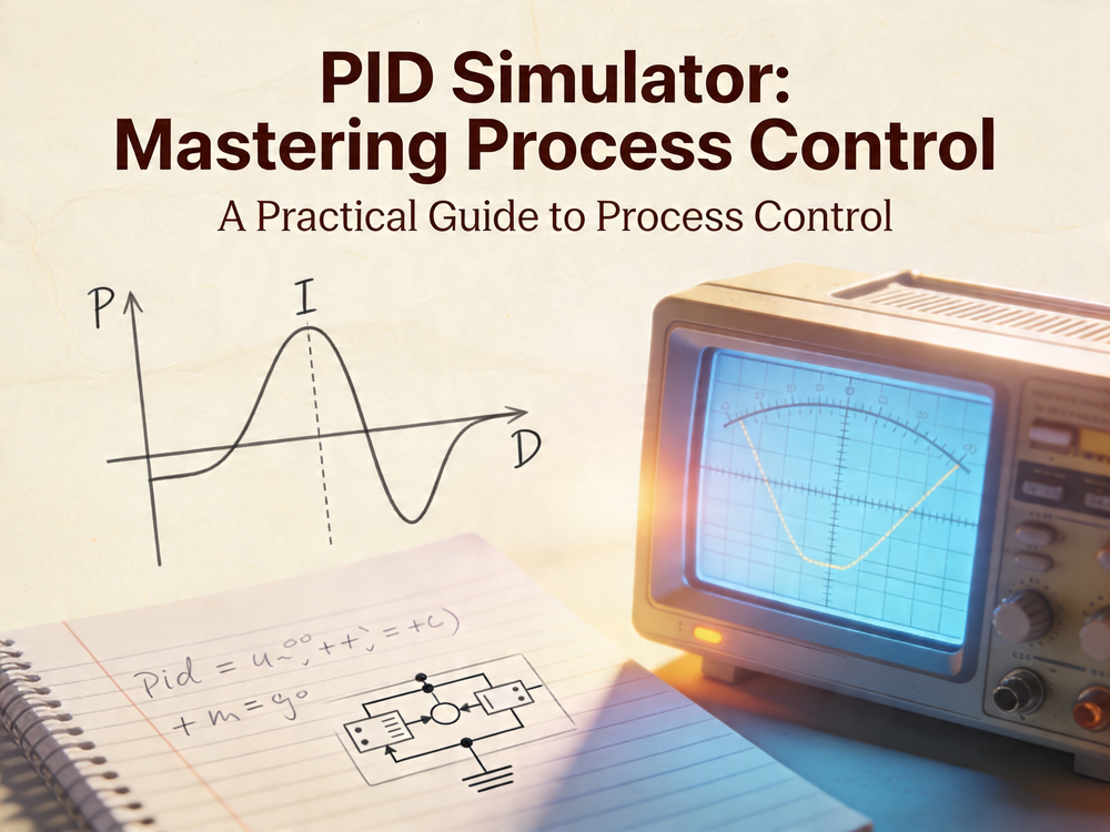
Joshua Bardwell finally built the thing many FPV pilots needed years ago: a simple simulator that shows what a PID controller is actually doing. The short version is this: P pushes, D brakes, I cleans up bias, and feed forward cheats the delay. It helps you to play around to see how the various parameters interact. You can play around with the interactive PID simulator below.
Why this simulator matters
Explaining PID with words only works up to a point. A real quadcopter adds too many moving parts, too much risk, and not enough patience. Bardwell’s simulator strips the problem down to one axis, one target, and one follower.
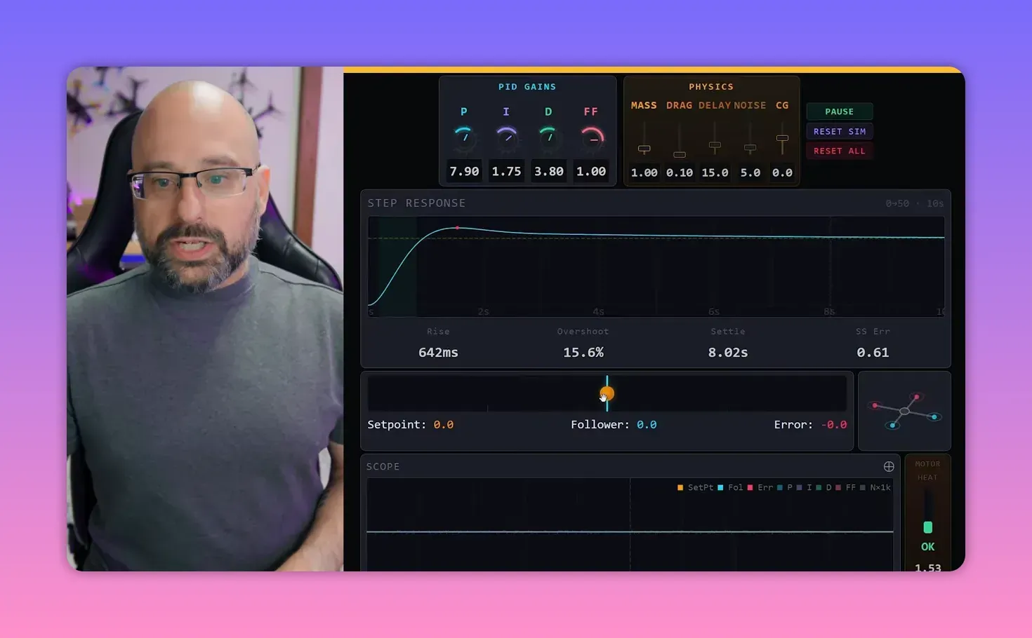
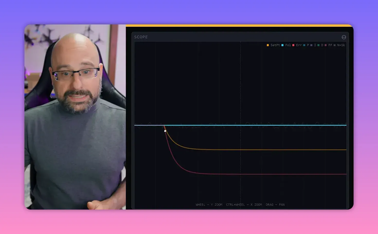
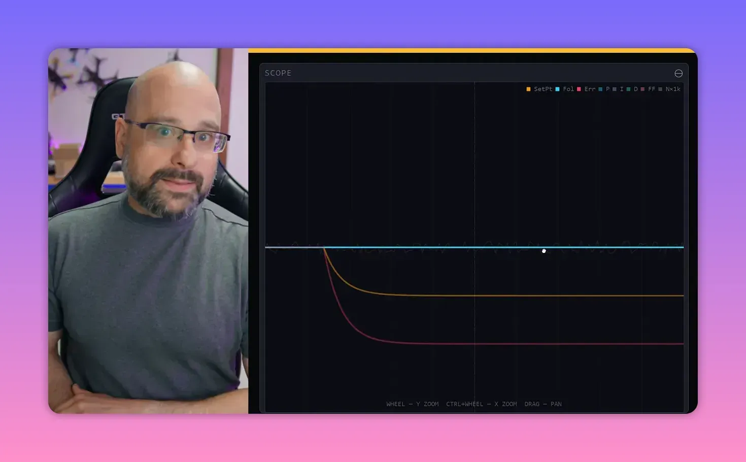
The model is simple on purpose. An orange handle marks the set point. A blue line marks the follower. The controller’s whole job is to make the follower track the set point as closely as possible.
That setup matches a real PID system. A thermostat targets a chosen room temperature and adjusts heating or cooling until the measured temperature follows it. Same pattern, less propeller violence.
The app’s four control tools
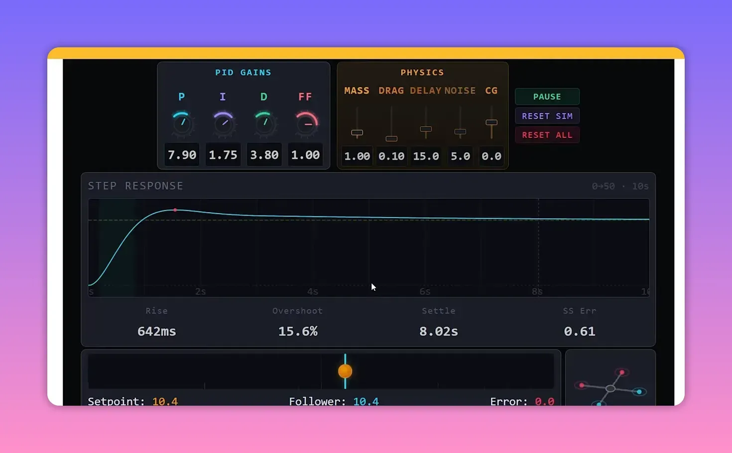
The simulator gives the controller four knobs: P, I, D, and feed forward. Bardwell starts by zeroing all of them, because the cleanest way to understand a control system is to break it first.
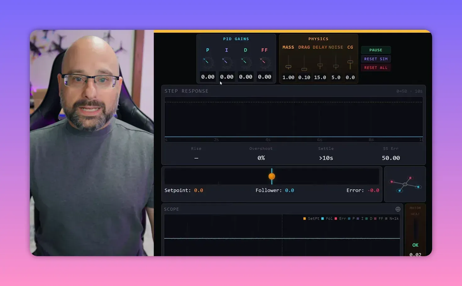
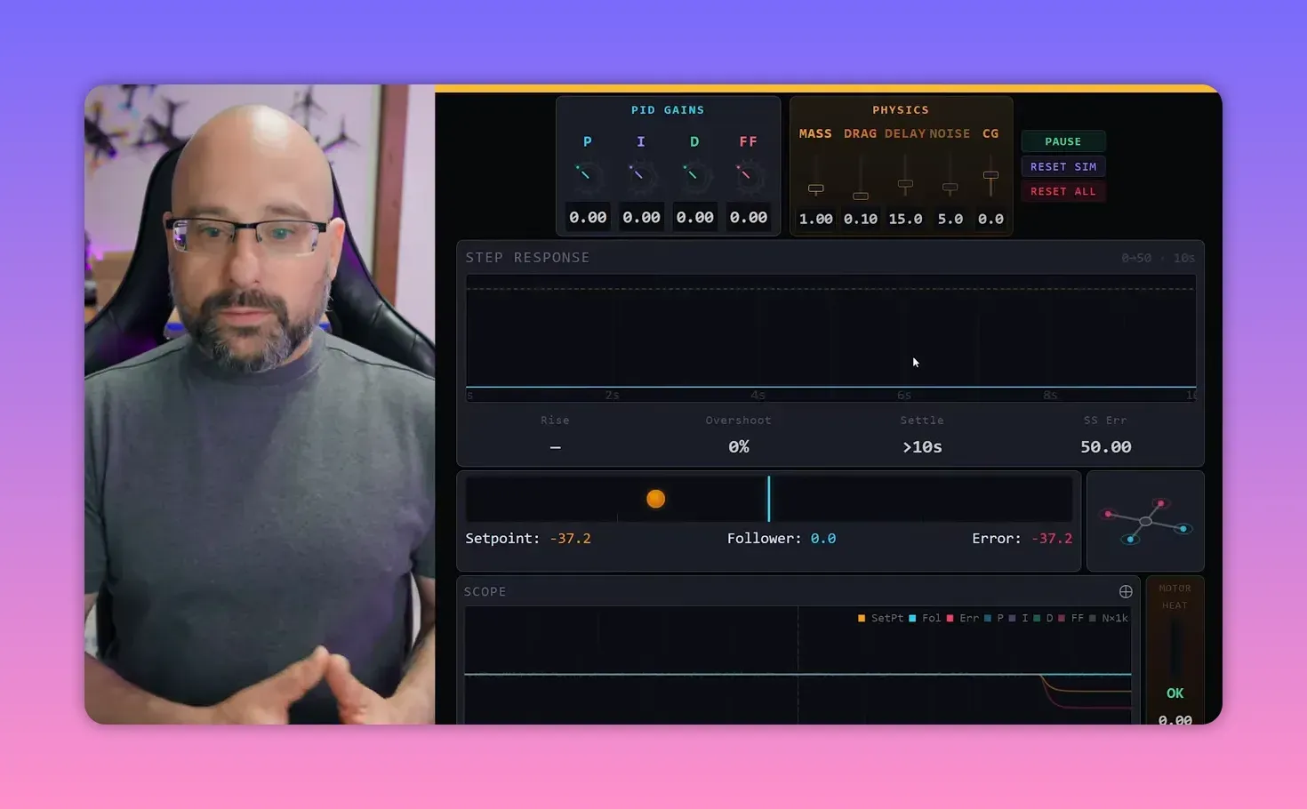
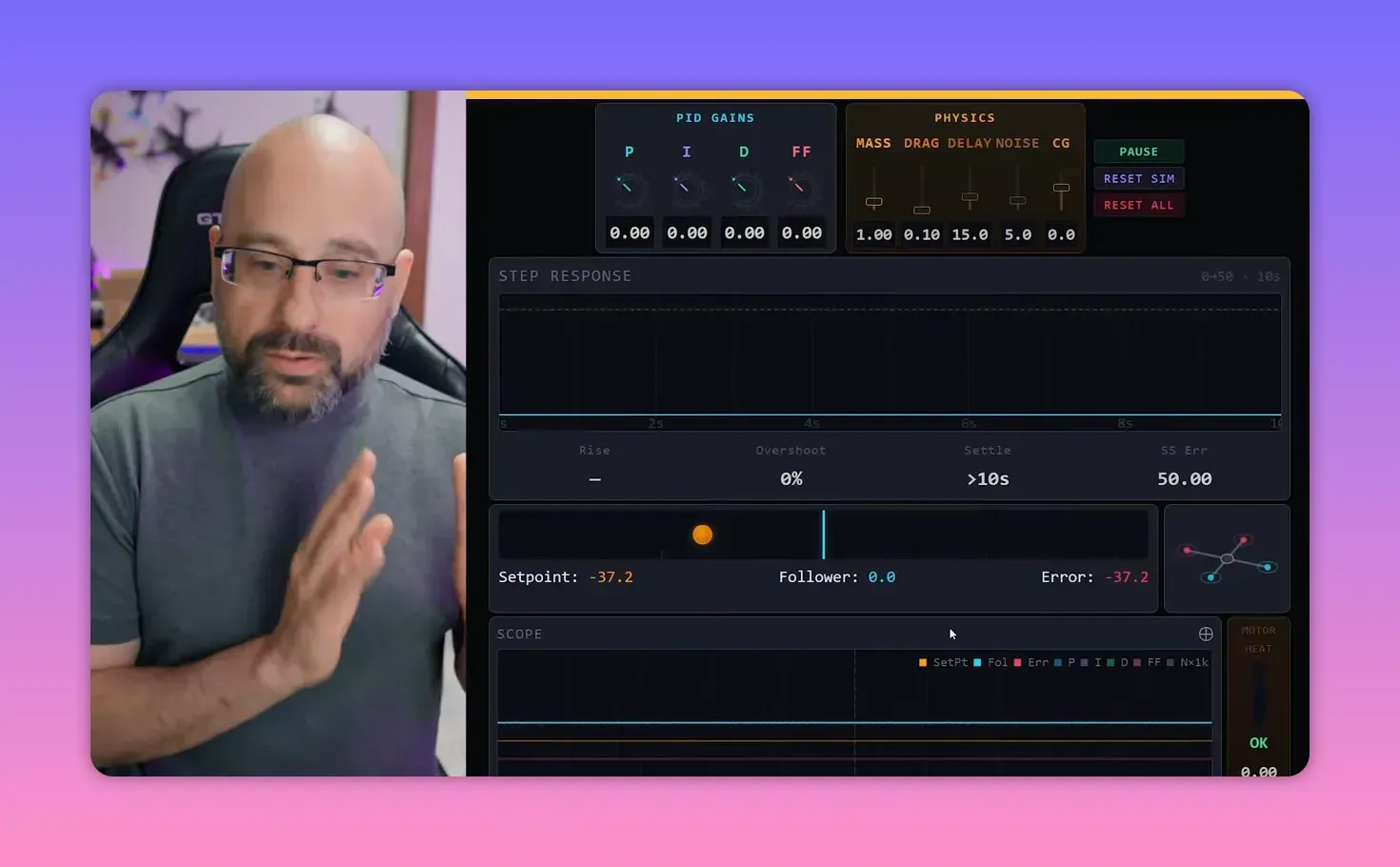
With every gain at zero, moving the set point does nothing to the follower. Error grows, and the controller just sits there like a committee waiting for another meeting.
How to read the scope
The scope is not decoration. It is the bridge between this simulator and real Blackbox logs from Betaflight. Learning to read it here makes real PID tuning less mystical later.
The colour coding is straightforward:
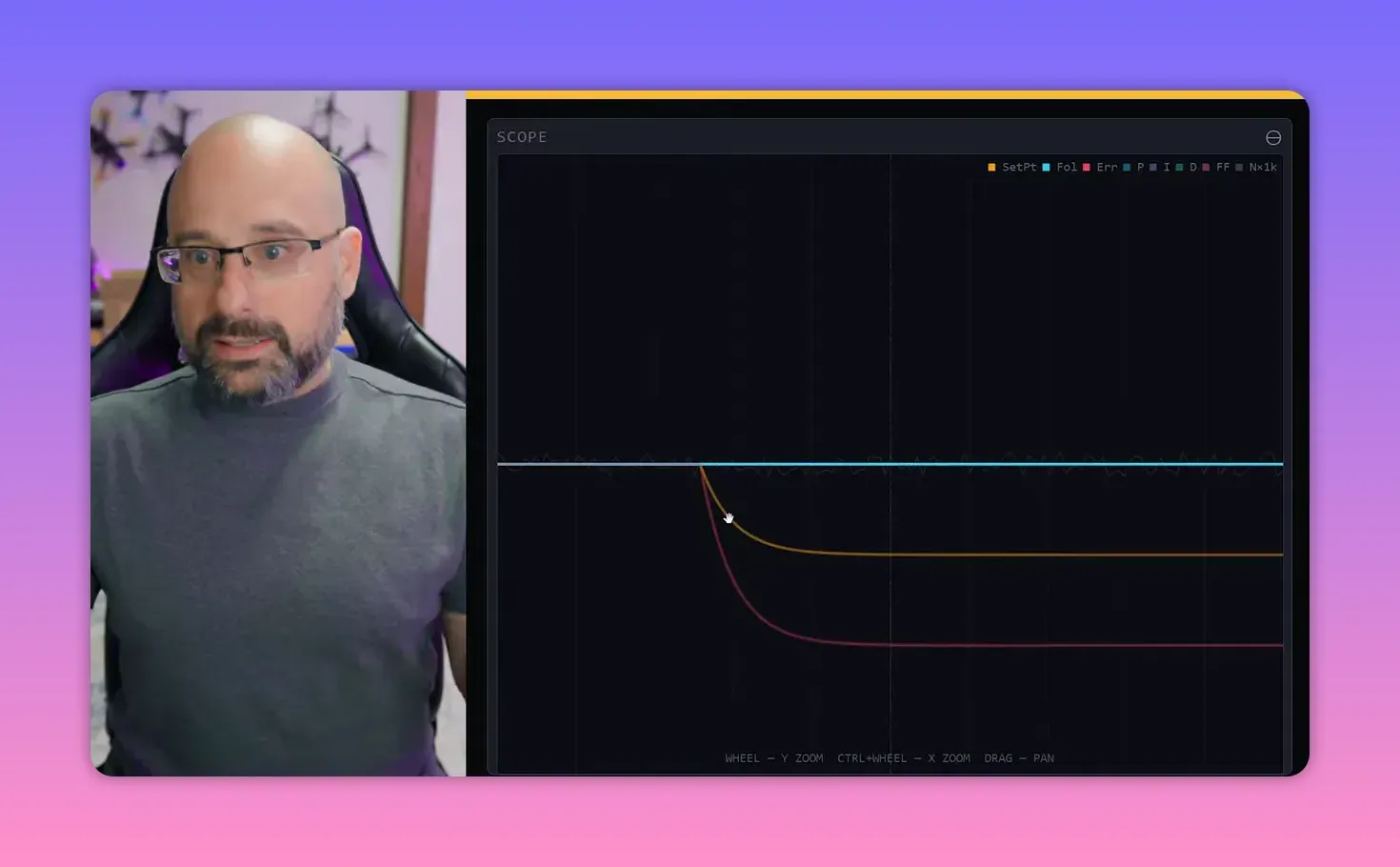
- Orange: set point
- Blue: follower
- Red: error, which is the difference between set point and follower
In the ideal case, the blue line sits on top of the orange line, and the red line stays at zero. That is the whole mission statement for a PID controller.
What P gain does
P stands for proportional. The farther the follower is from the set point, the harder the controller pushes it back toward target.
That idea is intuitive. Big error gets a big correction. Small error gets a small correction. In this one-axis world, the controller only pushes left or right.
Add a little P gain, and the follower starts moving toward the set point. Move it farther away, and the acceleration gets stronger because the error is larger.
Why P causes overshoot and oscillation
P gain fixes one problem and creates another. As the follower approaches the set point, the P term shrinks. At the exact instant the follower reaches target, P is zero.
But the follower still has velocity. So it sails past the set point, overshoots, and the controller starts pulling it back the other way. That creates oscillation.
With realistic P values, the oscillation is smaller. It still happens, though, because P alone does not know how to slow the system before impact.
Why oscillation sometimes settles down anyway
The simulator also models mass and drag. Mass adds inertia. Drag acts like friction. They are not part of the PID controller, but they shape how the system behaves.
In a frictionless world, one shove would send the follower moving forever. P would keep bouncing it back and forth. Add drag, and that oscillation damps out.
Bardwell keeps drag fairly low so the controller’s behaviour stays obvious. That is sensible. If the physics solves everything, the PID lesson gets lost.
How to read the step response
The step response graph is where the behaviour becomes measurable. It shows how the follower reacts over time after a change in set point.
With P alone, the follower rises toward target, overshoots, crosses back, and oscillates. Raise drag, and the same response damps faster.
This matters because PID Toolbox in the real world also shows step response. The difference is that the simulator computes the whole system directly, while PID Toolbox estimates step response from gyro data taken during flight.
That makes this simulator good training. A pilot can learn what a bad step response looks like before trying to interpret a Blackbox log after a field session and a questionable landing.
Too much P and the quad “flies away”
Raise P high enough and the oscillation stops shrinking. Raise it further and the oscillation grows. The app marks this as unstable.
In the simulator, the follower shoots off-screen. In a real quad, the result is the familiar angry twitch or sudden runaway when throttle comes up and the craft decides it has had enough of Earth.
Why delay causes instability
The villain here is delay. Real flight controllers do not act instantly. They read the gyro, compute a correction, tell the motors, and wait for the motors to respond.
That delay means the controller can apply the right correction at the wrong time. By the time the push lands, the craft may already have crossed the set point, so the “helpful” correction makes the oscillation worse.
With delay set to zero, instability disappears. The oscillation always tends to shrink, with drag mopping up the rest. Add delay back, and unstable feedback becomes possible again.
That is why low-latency control loops matter so much in flight control. Every bit of delay makes unstable feedback easier to trigger. Every bit removed gives the controller more room to work.
What D gain does
D is the derivative term. In plain language, it pushes against motion. The faster the follower moves, the harder D tries to slow it down.
People often call D “damping”, which is useful but incomplete. It is not constant friction. It scales with velocity. Slow movement gets little D action. Fast movement gets a lot.
That makes D a dynamic brake. P shoves the system toward target. D stops it from barging through the front door and out the back.
How to balance P and D
A good step response reaches target quickly with limited overshoot. Those two goals fight each other.
Raise P and the rise time gets shorter. The follower reaches target faster. Raise it too much, and overshoot and ringing get ugly.
Add D and the ringing settles down. That invites the usual temptation: keep cranking both gains until the graph looks perfect. Physics, of course, has other plans.
Why noise limits D gain in the real world
In the simulator, the next limiter is the noise slider. This models sensor noise and vibration in the gyro signal.
D gain hates noise because derivative action amplifies high-frequency content. In a drone, that means motors work harder, run hotter, and in bad cases produce smoke instead of thrust.
Bardwell represents this with a motor heat readout. Increase D too far, or inject too much noise, and the motors heat up fast.
The lesson is simple:
- If motors come down hot, reduce D gain.
- If motors heat up at modest D gain, the system is noisy.
- If the system is noisy, mechanical and electrical cleanup matters before tuning gets fancy.
Real-world noise comes from vibration, frame resonance, loose screws, cracked carbon, and electrical junk on the power rail. A good frame, tight hardware, sound carbon, and a capacitor all help.
Lower noise gives more D headroom. More D headroom allows more P. More P and D together give a faster, cleaner response. That is why a mechanically bad quad tunes badly no matter how heroic the slider work gets.
Too much D also slows the system
There is another catch. Even with minimal noise, too much D increases rise time because it resists motion. A graph with no overshoot can still be worse if it gets there slowly.
This is a nice corrective to the common obsession with “perfect” traces. A little overshoot paired with fast lock-in often feels better than a sluggish response that looks tidy in a chart.
Bardwell’s preference leans toward lower rise time with modest overshoot. That tends to feel sharper on a quad, especially when the overshoot is brief enough that it is barely noticeable in flight.
What a good step response looks like
There is no single holy graph, but the target is clear:
- Rise to target quickly
- Avoid large overshoot
- Avoid sustained ringing
- Keep motor heat in a sane range
If a tune gives a quick response, small overshoot, and only slightly warm motors, it is probably in the useful zone rather than the internet-comment zone.
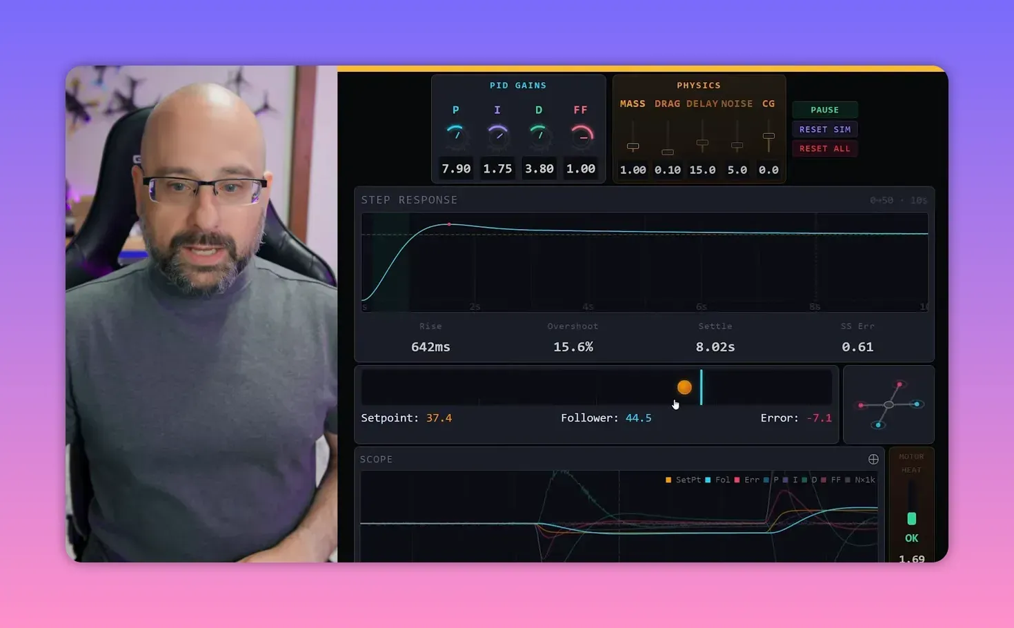
How to interpret P and D traces in the scope
The simulator also helps with reading individual PID terms on the scope. That matters because real Blackbox traces are not polite enough to annotate themselves.
In a real drone, the set point comes from stick position. In Betaflight, that appears as RC Command. The follower is effectively the gyro trace, which reports the craft’s actual rotation.
As set point and gyro diverge, error grows. The P term rises in proportion to that error. Then, as the craft starts moving, the D term pushes against that movement.
When the follower nears the set point, error falls, P falls, and D also fades as velocity drops. That sequence is easy to see in the simulator and much less obvious in a messy flight log.
What the I term does
I handles constant offset. If the system has a persistent bias, P and D may stabilise it near target but not exactly on target.
Bardwell simulates this with a CG slider. Shift the centre of gravity and the follower experiences a constant pull to one side, like a quad that wants to tip forward because its mass is not centred.
With only P and D active, the system stops with a steady error. It does not fall away forever, but it never quite reaches centre either.
I term solves that by accumulating error over time. If the controller has been “slightly wrong” for long enough, I keeps growing until it supplies enough steady correction to cancel the bias.
A neat mental model appears here: P looks at the present, D looks at the future, and I looks at the past. It is not textbook maths, but it is a useful shorthand.
iTerm windup, or how yesterday’s problem ruins today
iTerm windup happens when error persists for a while, I builds up, and then the correction finally arrives all at once. The system overshoots in the other direction and takes time to settle.
In the simulator, that happens on a slow timescale. On a real drone, it can happen in fractions of a second. A full roll is a classic example: error accumulates during the move, then I kicks in after the move stops and creates bounce-back.
That bounce can resemble P overshoot, but the feel differs. iTerm windup is slower and softer. P-term bounce is sharper and faster.
Modern flight firmware largely suppresses this. During fast movement, I is reduced so it does not stack up error uselessly. It becomes more active again when motion slows and steady correction matters.
What feed forward does
Feed forward is different from P, I, and D because it does not react to actual movement or actual error. It reacts to input.
The basic idea is that the quad will always lag a stick movement if the controller waits for error to appear first. Feed forward skips the waiting and starts pushing the craft the instant the stick moves.
Set P, I, and D to zero and apply feed forward alone, and the effect is obvious. Move the set point and the follower gets a shove in that direction. Then the shove stops.
Why does it stop? Because feed forward only responds while the input is changing. If the stick stops moving, feed forward goes to zero. It does not care where the set point is sitting, only that it moved.
That also means feed forward cannot work by itself. It supplements PID. It gives the initial kick, while P, I, and D keep the craft on target after the command starts.
What this teaches about real PID tuning
The simulator is not a substitute for Blackbox or PID Toolbox. It is the missing conceptual layer that makes those tools easier to use without cargo-culting somebody else’s tune.
The practical tuning logic it teaches is solid:
- Raise P to reduce rise time
- Use D to control overshoot and ringing
- Keep noise low so D does not cook the motors
- Use I to correct constant bias
- Use feed forward to reduce input lag
That is the kind of understanding that makes flight logs look less like modern art and more like a system with causes and effects.
FAQ
What is the main goal of a PID controller?
Its goal is to keep error at zero. In this simulator, that means making the follower sit exactly on the set point, with no sustained gap between them.
Why does P gain create overshoot?
Because P decreases as error shrinks. When the follower reaches the target, P is effectively zero, but the follower still has momentum and keeps moving past the set point.
What does D gain actually do?
D opposes motion. The faster the system is moving, the stronger D pushes back. That makes it useful for controlling overshoot and reducing ringing.
Why do high D gains make motors hot?
Because D amplifies high-frequency noise. On a real quad, gyro noise and vibration turn into rapid motor commands, which raises motor temperature and can cause damage.
What is iTerm windup?
It happens when error accumulates over time, I builds a large correction, and that correction arrives after the original condition has changed. The result is a slower bounce-back in the opposite direction.
How is feed forward different from P, I, and D?
Feed forward responds to stick input itself, not to measured error or motion. It starts the move early, before the normal feedback terms have had time to react.
What does a good step response look like?
It reaches target quickly, does not overshoot too much, settles without ringing, and does not demand so much D gain that motor heat becomes a problem.
Takeaway box
P gets the craft moving, D stops it from being dramatic, I fixes steady bias, and feed forward jumps the queue.
Too much P plus delay creates unstable feedback. That is how a quad turns a bad tune into an argument with gravity.
Too much D does not just fix oscillation. It also boosts noise and heats motors. A mechanically bad quad is a tuning tax.
A “perfect” graph is not always the best tune. Fast rise time with modest overshoot often beats a slow, sterile response.
If Blackbox traces seem cryptic, this simulator is the missing Rosetta Stone. It shows what the terms do before the field repairs begin.
This article was based from the video This app TEACHES YOU how a PID controller works