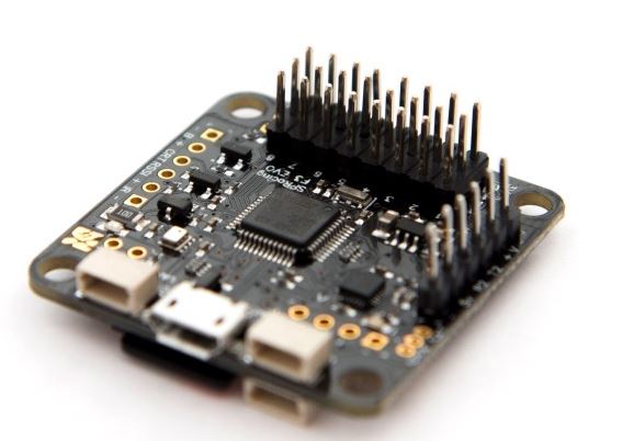
The SP Racing F3 Evo flight controller is built for FPV Racing. It is designed to use the latest and greatest hardware while keeping the board cost to a minimum, at the end of the day when pushing your FPV racer to the max you will eventually crash, so having an affordable flight controller with incredible performance means that you can push a little harder, or try something new without breaking the bank if you crash.
SP Racing F3 Key Features
- Micro SD card reader – can record flight data logs easily onto and SD card (not limited to 128mb like on other flight controllers)
- Stackable – Can mount onto compatible PDB’s or OSD’s with just 2 through hole pins in each corner.
- Next Generation CPU and Sensors – Using the ARM Cortex-M4 72Mhz CPU along with MPU9250 connected directly via SPI (8Khz sensor update rate), to ensure processing of more sensor data than ever before.
SP Racing F3 Evo Pinout

The UART2 port is primarily used for R/C input, be it PPM, SBUS or Spektrum, there is a variety of connectors for each. If you connect your R/C reciver via PPM then you can still use the UART2 out to send telemetry info back to your receiver (such as an X4R, or D4R). However if using spektrum or and SBUS receiver then the UART2 out cannot be used.

On the bottom of the F3 Evo is the microSD card reader to store black box flight logs. But you will also notice two solder pad jumpers. The first is to select between using an IR LED Transponder (for race timing) or an LED RGB. The second pad is to select between your RSSI input to be analogue, or PWM (depending on your receiver). Simply solder two of the 3 pads together to enable on or the other as described on the image.
Typical Connection Diagram
The diagram below is a typical connection for a FPV racing quadcopter. There are some things that you can do differently, but this is just as a guide if you have no idea on what to do. This diagram connects the receiver in PPM mode (so that you can still use the same UART port for telemetry out). Also I am using the RGB LED instead of the race timing transponder as I dont consider myself a good enough FPV pilot to race yet 😛

But if you are using the IR transponder (which is a good reason to get the SPracing F3 Evo flight controller) then the diagram below shows a more typical race drone setup. We are also using SBUS since its technically faster than CPPM so there is less lag between the controller detecting your signals compared to CPPM (But we are talking about miliseconds).

If you have no idea what I mean by CPPM, or SBUS check out our R/C Protocol guide.
Pin Headers
The F3 Evo flight controller includes right angle and straight pin headers with the kit which gives you the flexibility to mount the board in a variety of ways. Using right angle headers are best if you dont have much vertical space, and straight headers are best if you dont have much horizontal space. For other frames like the nighthawk X, you might need to solder the wires directly and not use any pin headers.
As in the photo above you need to use the tripple row headers along all the ESC connectors, and then the single row straight pin headers alon the left side where the R/C input pins are located. If you plan to use a spektrum receiver, you should rather solder the spektrum satellite connector.
Install Drivers and Cleanflight
If you have never used any cleanflight boards before the first thing is to download and stall the cleanflight GUI and the drivers for the SP racing board. Windows might install the correct drivers automatically, but its usually best to download and install them yourself.
- STM32 Virtual COM Port Driver
- Cleanflight Configurator tool (chrome extension)
Connecting your receiver
There are 3 main way people connect their receivers to ther flight controller (ok actually 4 if you caount PWM, but thats not an option with the F3 Evo since its 2016 and if you can avoid it, dont use PWM as there are just too many wires!). So the 3 ways you can connect your receiver to the F3 Evo is via PPM, SBUS, or Spektrum.
Because we are a big fan of FRsky radio gear we will be using the XSR receiver in these diagrams, but you can just as easily use something like a X4R-SB, or D4R receivers as all of these are nice and small, making them suitable for FPV racing quads.
Setup Taranis Mixing
If you have not setup a model on your taranis check out this post which shows yo how to setup mixing on your taranis for a basic setup
PPM Receiver

I usualy prefer to use PPM for my recievers,because it means that you dont need to use a dedicated UART port to read the signal (like you do with SBUS). Freeing up a UART port so you can use it for other functions. But since the F3 board has 3 UART ports this is less important. In the diagram above you can see that I can use the same UART port to send telemetry back to the XSR, which I talk about later in this guide under the telemetry section.

SBUS Receiver

If you prefer to use an SBUS receiver you still connect it to the UART2 port as shown in the diagram. However SBUS uses the entire UART port so if you also want to use telemetry you need to use another UART port. In this case I am using UART1 as that keeps the UART3 open so we can use that for an OSD.

Using Smart Port Telemetry
Using telemetry is fairly useful on your FPV quadcopter as it lets you send some information such as your battery voltage back to your radio so you can easily see how much longer you can fly for. With the FRsky Taranis you can even set it up to use voice output to say how much voltage your battery has. You can also possibly do this with other radios but I have not used them so am not too sure how to do that.
As shown in the diagrams above you will need to use a receiver compatible with telemetry (such as FRsky X4R, X6R, X8R, XSR), and simply connect one of the spare UART TX pins to the telemetry input on your receiver. In the case of a PPM receiver you can use UART2 TX, but if using SBUS/Spektrum you will need to use UART3 TX. Then in the ports section of cleanflight make sure to select SmartProt from the telemetry dropdown (dont select FRsky telemetry as that is an old protocol).
Enable Telemetry Inversion
With Frsky smartport telemetry you will need to invert the telemetry signal from your cleanflight controller. Fortunately since the F3 Evo uses an F3 processor that has a configurable hardware inveter so you dont need to make up any special cable. Just go to the CLI and type set telemetry_inversion = ON and hit save.
Then the last thing to do is to make sure telemetry is enabled on the configuration tab
Setup your Taranis
The final thing is to enable the sensor data onto your taranis.

- Go to the taranis telemtry screen and select the option
Discover new sensors. - New sensors from cleanflight should appear in the list.
Cleanflight does not send all sensor data when it is disarmed, so its best to arm your board before searching for the sensors on your taranis to make sure they all appear. Just make sure you remove the propellers first!
- Once you have found the sensors simply select
Stop Discovery
Here is a great video that walks you through the process of setting up telemetry on your taranis using an XSR receiver.
Connecting an RGB LED
If you plan to use an RGB LED with your F3 Evo flight controller then you cant use the timing transponder at the same time, as you can only use one of the other. You select which one you want to use via the IR/LED jumper selector on the back of the board as shown below.

In the case of the RGB LED then you need to solder the right arrow and the square pad together to enable the RGB LED mode.
Programming your RGB LED’s in cleanflight
The video below shows you how to program your RGB LED’s in cleanflight to perform various functions, the guide itself is actually for a Naze32 board, but at far as cleanflight is concerned, its exactly the samem just connected in a different location with the F3 Evo.
Race Timing Transponder
The racing timing transponder makes this board one of the must have boards for FPV racing events, the IR transponder broadcasts a unique code that allows the iLap timing systems to record your lap times as you fly past. Unlike the F3 Mini board (which allows for 2x IR LED’s) the F3 Evo has only 1 IR LED. This means you need to check at the event which side you need to mount your LED in order for the timing system to detect your drone. In general its probably a good idea to mount the LED on some wire so you can move it to either side of your drone depending on the situation.

Remember that longer leg of the LED is positve, and also remember to solder the jumper on the back of the board to select IR LED mode.
Setting up your racing timing transponder
With each official SPracing F3 Evo board you will receive a QR code which is unique to that board, you simply need to enter that QR code in the race transponder screen to activate the device.

Also remember to enable the transponder on config tab, in the other features box.
Flight Data Logs (Black Box)
Because the F3 Evo uses a microSD card for flight log recording, you can literaly record every possible parameter as fast as possible and never worry abot running out of space! You can use microSD cards up to 32GB with this, so that sure it alot of logs!
For more details check out or black box setup guide

Connecting OSD
If you want to use a micro minim OSD, you just need to hook it upto one of the UART ports on your F3 Evo, in this case I am using the UART3 port as it provides power for the OSD board which is super us full.

To learn how to setup your flight controller check out this setup video, it is written of the regular F3 board, but the principles are the same.
Any Questions/ Suggestions?
So hopefully this well help you get setup with the awesome F3 Evo flight controller, should you have you have any questions, comments or tips be sure to add them in the comments below. Happy flying!


